Best electromechanical products according to redditors
We found 830 Reddit comments discussing the best electromechanical products. We ranked the 452 resulting products by number of redditors who mentioned them. Here are the top 20.
We found 830 Reddit comments discussing the best electromechanical products. We ranked the 452 resulting products by number of redditors who mentioned them. Here are the top 20.

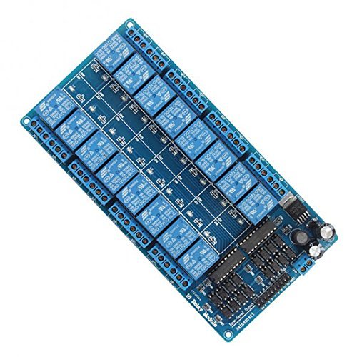


The way I do it is with an Arduino and a 16-Channel Relay Module.
http://arduino.cc/
http://amzn.com/B0057OC66U
If you want the actual sound to play outside, you can do that with a sound board, speakers, and a cheap power supply.
http://www.adafruit.com/products/2217
Then you program the lights to trigger however you want.
This is my induction heater.
I got the idea because I thought that some of the colors and textures in this (dark wood, glass, copper coiled wire, metal) reminded me of an olde-tyme'y "Edison lab" or "steampunk" theme.
So, I prototyped a build in this container. Parts list below, for those interested:
​
Parts List
​
Miscellaneous parts:
It should be possible to play the whole game using the keyboard. Before you think it sounds foolish, it'd open up a lot, including the ability to playback macros. Think the clone tool on steroids. People could share sections of their prisons and you could import them by running the macro into your own prison. It'd also help people who have problems using the mouse for extended periods of time but have no problems typing.
Also, how cool would it be to have a button you could hit with your hand to lockdown the prison?
With that button you'd have to do some DIY work and put some USB guts inside, but it'd be significantly more durable than this mostly-ready-to-go option.
Edit: There might be a better way of going about it (I haven't much experience), but it seems using this as the guts should make it work (I was adapting from this guide and Peterjaap's comment on on the same page where he substituted the Teensy for the Trinket).
Right here: http://www.amazon.com/gp/product/B0057OC5O8/ref=oh_aui_detailpage_o00_s01?ie=UTF8&psc=1
internal shot
Parts list:
Tools:
STL for 3d printing:
All three files
Wiring diagram:
Terrible MS paint Diagram
I'm not really pro-grade in this kind of stuff, however, if I were to go after something like this, an Arduino seems almost perfect. For anything you need to control, I'd use this type of relay designed to plug straight into Arduino IO pins and as far as the inputs, you could probably use relays wired up to a simple 5v source so you isolate the power within the pinball machine from clean 5v power for your Arduino.
As far as the display, instead of an LCD, I would probably chase some larger 8-segment displays, easier to see and much easier to control. One option would be to run 2 Arduino systems with one dedicated to the scoreboard and one dedicated to the automation.
ok, ramble off, but this sounds like a project I'd like to take on now...
I've got a relay from amazon connected to some of the GPIO pins, then a simple website I made on the pie that when I press a button on it, it flips the relay. The relay is wired to the door open button and does the same thing as me physically pressing the button in the garage. I also have it monitoring for an amazon dash button press that will also trigger the relay, that is by the front door so I can open the garage on my way out the door if I need.
​
However, this has all been running for 4+ years, I tried to review how I pieced it all together about a year ago and couldn't remember or figure out all the pieces, but it still continues to work, so I can't give much more detail than that sorry.
I moved shops recently and wanted to have piped dust collection so I started working on that. Somewhere while watching some videos I saw several where people had blast gates that switched the DC on and off and I was like that's awesome but they didn't go into much detail. I finally accidentally found one that gave a better idea of what products they used and bought the parts, tested it out and implemented it. It works great.
To turn on the collector I just open a blast gate. To turn off the collector I close the blast gate. Pretty simple and it makes it very hard to forget to close a blast gate and use another tool with reduced suction.
Short video of it in action: https://www.youtube.com/watch?v=59u5zHttUn4
The parts I used:
Edit: Oh and of all the methods I used to cut the DWV piping (bandsaw for shorter pieces and cleaning up, sawzall with a crappy miterbox-style 90 cutting guide and a handsaw in the same guide) the handsaw I think was the easiest to get a nice cut.
That's gorgeous. Great work.
My only thought is it's absolutely perfect if you add a safety power switch. A very small detail, but might make a big difference. https://www.amazon.com/Woodstock-D4160-110-Volt-Paddle-Switch/dp/B005W17HYY
This is my parts list.... Simple and it works
The enclosure I used: https://www.amazon.com/dp/B07TS6RY85/ref=cmswrcpapaiAyhxDbV7EHBCN
The 5A power supply (5A and you don't have to use a mosfet): https://www.amazon.com/dp/B01461MOGQ/ref=cmswrcpapaiGzhxDbQWPT5QR
I used a glass slide tube for inside of the coil. You will have to rewrap the coil on the IH to fit around the slide, not hard at all: https://www.amazon.com/dp/B001FWYAWQ/ref=cmswrcpapaiMAhxDbTK5P2YY
The actual IH: https://www.amazon.com/dp/B01GDVVANA/ref=cmswrcpapailChxDb0DGE3TM
The 5v switch w/ wiring harness (you don't need any extra wires this way): https://www.amazon.com/dp/B075QBJVTS/ref=cmswrcpapaifDhxDb7HTYE19
A Unibit would be a good thing to have to get the 3 holes drilled in the box. A hotglue gun and a screwdriver and your set....
Ulincos Latching Pushbutton Switch U19C1 1NO1NC SPDT ON/OFF Black Metal Shell with Blue LED Suitable for 19mm 3/4" Mounting Hole (Blue) https://www.amazon.ca/dp/B017KP67FY?ref=yo_pop_ma_swf
Yeeco Waterproof LED Digital Battery Meter DC 12V 24V 36V 48V 60V 72V 84V 96V Acid Lead/Lithium Polymer/Lithium Iron Phosphate/NiMH Battery Capacity Indicator 6-120V Voltage Volt Meter Multi Tester https://www.amazon.ca/dp/B01MU6V9RD?ref=yo_pop_ma_swf
UTG Tactical Low Profile Rail Mount for Ruger 10/22 Rifle https://www.amazon.ca/dp/B002GNYCJ4?ref=yo_pop_ma_swf
Valken Rifle Accessory Offset Ring Mount, 1" https://www.amazon.ca/dp/B01IU9DV8K?ref=yo_pop_ma_swf
Angled Wedge Hard Rubber Riser Pads with 1.5" Screws (Blue) https://www.amazon.ca/dp/B01LDO3NZU?ref=yo_pop_ma_swf
Bones Bearings Bones Reds Precision Skate Bearings https://www.amazon.ca/dp/B000FDRQ1S/ref=cm_sw_r_cp_apa_gC.RBbKB0KG0H
Homyl Aluminum Alloy Skateboard Longboard Anti Sinking Gasket Prevent Sag Washer - Black, as described https://www.amazon.ca/dp/B07BKS964N/ref=cm_sw_r_cp_apa_SC.RBbNY1EJVH
https://rover.ebay.com/rover/0/0/0?mpre=https%3A%2F%2Fwww.ebay.ca%2Fulk%2Fitm%2F132701686112
No worries, sounds like you only have the cell right now. I'll skip all the safety stuff but I will say, if you aren't absolutely positive what you are doing, stop. The lowly NA outlet has a tremendous current surge rating. You'll die and never know it. Before continuing, you do absolutely need to know your outlet is wired correctly and you'll want to confirm which part of your circuit is the live or hot wire.
Do you need AC or DC to operate your cell? If you can operate it on AC, you'll only need a heavy 3 prong power cord, the circuit board in the link above and a fuse holder and fuse rated for the power input required.
If you need DC then you'll also need a bridge rectifier rated (guessing) 35 amps.
Since you don't yet know the actual circuit current, you'll need some device to monitor the incoming power. Here is what I'd do:
Before plugging this death trap into the wall, confirm you have a 2-5 amp fast blow fuse Installed in the fuse holder. We only want to initially tickle the dragon. Double check the device is turned off. This one looks more beefy:
https://www.amazon.com/DROK-Regulator-Controller-Temperature-Governor/dp/B00BXUCWQG/ref=pd_sbs_60_2?_encoding=UTF8&pd_rd_i=B00BXUCWQG&pd_rd_r=SCK4RH8538ARSNVKPSVS&pd_rd_w=WLQ1A&pd_rd_wg=qgTGd&psc=1&refRID=SCK4RH8538ARSNVKPSVS
Hide your wife and kids, connect to power while shielding your eyes.
You should now be able to slowly turn up the power while monitoring the input current. You really need something to at least be able to look at how much current you are pushing.
If all goes well, swap the fuse to something in the 10 amp range and keep slowly turning it up.
If you need DC let me know own and I'll draw something up for you.
If you have even the smallest question about anything I've said ask. Please. I don't want to hear about anyone on the news..
UPDATE:
That site seems to aim toward 12 volt DC hho cells. At 1100 design watts that's pushing nearly 100 amps! Is this part of your design? To run that off of a standard 110 volt AC outlet, you are definitely going to need a large power supply. Again, I can help but it likely isn't going to be cheap unless you are ready to scrounge and learn more about electricity.
SSR or Solid State Relay. It's a switch to turn line voltage power on and off using low voltage (3-32VDC).
Here is one on Amazon with a heatsink.
5pk 3v relays from Amazon. I had to get these when I switched from 5v Uno to 3.3v ESP32. My 5v relay wouldn't recognize the 3.3v as a high signal. Using to control 24VAC garage furnace.
Only 10 bucks!
http://smile.amazon.com/SainSmart-4-CH-4-Channel-Relay-Module/dp/B0057OC5O8/
From personal experience:
LEDs? Yes. Absolutely.
Headlights and wipers? Yes, but the motors on the wipers would be interesting.
7 inch touch screen? There's one built for the Pi already.
Buttons? Yep. pygame could be written to handle all of that. I'm sure other languages could be used, that's just what I'm most familiar with.
10-15 relays? Yep. I personally use a 16-port mechanical switch for a project here at home. You can narrow that down to just a few pins if you know how to program an i2c.
5-10 analogues? Probably. Not sure how many GPIO are left over after using 16 for a relay.
Phone connecting via bluetooth? Not my area, dunno. I suspect so.
Will the Pi handle all of that simultaneously? Heh... easily. The stuff you're talking about is very very simple. It's a lot going on, but the processing power it requires would be hardly nothing at all.
I still would absolutely recommend against it. At least put the headlights on the 'on' position on the relay so if the pi dies, the headlights are auto-on. Take the wipers off of the Pi. That going bad in a rainstorm or snowstorm could be hell.
Sure! You'll need a relay to handle the higher voltage from wall outlet, or from the wiring in the strand itself. I have a 4-channel version of this that works great: http://www.amazon.com/SainSmart-2-CH-2-Channel-Relay-Module/dp/B0057OC6D8
If you want a finished solution, Belkin makes WeMo devices you can control from an iPhone or Android, or setup trigger with IFTTT: http://www.amazon.com/Belkin-Automation-Switch-Apple-iPhone/dp/B0089WFPRO
Not just from prusa, pick and choose. URLs for examples.
Digital caliper, 12" https://www.amazon.com/gp/product/B000EJUBBU/ref=oh_aui_detailpage_o02_s00?ie=UTF8&psc=1
Extra brass nozzles.
Hardened steel nozzle, 0.4mm to 0.6mm for printing abrasive exotics (wood, glow in the dark, carbon fiber etc)
Print removal tool https://www.amazon.com/gp/product/B00VB1U886/ref=oh_aui_detailpage_o02_s01?ie=UTF8&psc=1
Locktite blue bolt-fixer (Walmart, Home Depo, Lowes etc) to stop bed sensor from moving.
High temp anti-seize for nozzle threads https://www.amazon.com/gp/product/B0053ZS1Z8/ref=oh_aui_detailpage_o02_s01?ie=UTF8&psc=1
Raspberry Pi 3, 5v Pi 2A Power wart, Micro SD card, & Webcam for octoprint monitoring.
Relay board for Pi/octoprint to power up & down printer remotely. https://www.amazon.com/gp/product/B0057OC5O8/ref=oh_aui_detailpage_o04_s02?ie=UTF8&psc=1
1lb of silica gel to keep filament dry.
Filaments, various.
Fire extinguisher rated for electrical fires.
Dedicated smoke alarm.
hey man, about to build my first heater tomorrow, I have a list of parts I ordered based on several threads and stuff you and others recommend I came up with this:
https://www.amazon.com/gp/product/B0060U92FS/ref=ppx_od_dt_b_asin_title_s00?ie=UTF8&psc=1
https://www.amazon.com/gp/product/B071NCKQFW/ref=ppx_od_dt_b_asin_title_s00?ie=UTF8&psc=1
https://www.amazon.com/gp/product/B01G00GHQY/ref=ppx_od_dt_b_asin_title_s00?ie=UTF8&psc=1
https://www.amazon.com/gp/product/B00VNSO3OM/ref=ppx_od_dt_b_asin_title_s00?ie=UTF8&psc=1
https://www.amazon.com/gp/product/B003TUMDWG/ref=ppx_od_dt_b_asin_title_s00?ie=UTF8&psc=1
https://www.amazon.com/gp/product/B01GDVVANA/ref=ppx_od_dt_b_asin_title_s00?ie=UTF8&psc=1
aside from wires, a box and tools (Ill get tomorrow from work)
am I set or do I need anything else, also if any of those things I bought incomatible?
Insulation
Controller
High temp silicone
Supply cord
Thermometer
Elements
Insulation adhesive
So, this setup is certainly not perfect and has the potential for uneven heat disbursement but it has worked well for me.
I drilled 3 holes about 3 inches from the bottom of the cabinet for the heating elements and used thin aluminum stock cross members to support them. The holes were sealed with silicon which also helps keep the elements in place.
The entire inside of the cabinet has a layer of cut-to-fit insulation and the seams are taped with high temp flue tape.
I have 2 threaded steel rods running horizontally and offset for hanging parts.
The thermometer is at the top and generally runs a large number of degrees cooler than the parts but I have a good feel for time and tackiness when flashing and layering. I prefer longer cure times at lower temperatures. You can cure this stuff at 150 degrees if you want...it just takes a hell of a lot longer.
The rest of the stuff is just wired up and I'm sure its a huge fire hazard and I have zero experience with this kind of thing but it has worked for me so far without a problem. It's set up in my garage with tons of ventilation and a fire extinguisher close by.
Arduinos overlap quite a bit of PLC functionality. Instead of 24V, everything will be 3.3V or 5V. A PLC typically scans the ladder for inputs then executes everything "at the same time". In Arduino code, variables update immediately.
You'll probably want to look at Adafruit and Sparkfun for LCDs and buttons, as well as relay boards. Amazon carries some selection, but Adafruit and Sparkfun (for the most part) design and manufacture their own boards, so their support is a lot better. Note that if you use a lot of relays (>4), you'll need an external power supply to switch them all on at the same time since Arduinos can't provide enough current to drive tons of relay coils. The one I linked uses an external 12V supply, but I don't know if it's included.
Seems like it would be pretty simple - find a cheap/quiet air compressor, run the line through a normally-closed solenoid (found this for 11 bucks), and control the solenoid w/ the arduino. If the solenoid is higher than the 5V the arduino can supply, have the arduino power a relay or a power transistor, I use a 12 channel one of these to power solenoids for dispensing water and it works well. Sounds like y'all already have the code set up to do something similar, but give a shout if you need help with that part too
I'm currently struggling with the same problem with my project.
You'd probably want to put a DHT11 in each pot attached to GPIO on the Pi.
The soil RH (relative humidity) could be used to determine whether to power a 12v pump or solenoid valve (if gravity fed).
Relays are super easy to set up and control using a Pi and relatively safe at 12v. The difficult question here is how to direct the water into whichever pot requires what amount of water. A naive approach is one pump per pot but that could get costly... hmm
I'm using this pump
I'm using this relay
Here's the code to read digital Celcius and RH from the DHT
I'm also considering adding an additional 'misting' nozzle to help control my super-hot (not ideal) environment :
Soil > Tempenature : 37.0 Humidity : 77.0
Feel free to follow up in PM if you have any questions.
Here you go
for a beginner, I would not recommend you do this. but if you will anyway, I suggest this: http://www.amazon.com/SainSmart-101-70-101-4-Channel-Relay-Module/dp/B0057OC5O8/ref=sr_1_4?ie=UTF8&qid=1462302659&sr=8-4&keywords=3.3v+relay
The Wemo Switch can be wired to directly control the relay/contactor which should be more than enough.
You would just need to grab an enclosure and whatever plugs/outlets and a few bits of spare wire.
There are cheaper WiFi switches but I personally like the Wemo switches, you can set rules (like Auto-Off) or schedules and it works with IFTT for more advance stuff.
WeMo Light Switch, Wi-Fi enabled, Works with Amazon Alexa https://www.amazon.com/dp/B00DGEGJ02/ref=cm_sw_r_cp_api_8JkBybZJS8X0H
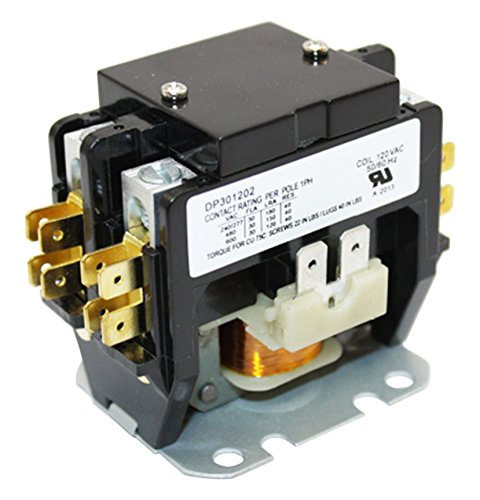
Packard C230B 2 Pole 30 Amp Contactor, 120 Voltage Coil https://www.amazon.com/dp/B001KGSJ74/ref=cm_sw_r_cp_api_1IkBybGQNQV6G
I threw something together that i think would work for your circuit
Honestly though i wouldnt do what your doing and run amperage through a keyswitch, for one its not really safe and two depending on what fridge you use + powering a RPI you could easily surpass the typical 10A the switches have when the compressor comes on and spikes. You may be able to get away with it though, but im a fan of using contactor relays to prevent this. It will add another $10 to the build but its a mechanical relay that can control your hot line via a key switch, and only put a few milliamps through the switch at any given time, this switch would control the 5V power supply which would power the RPI, basically identical to how an electric brew panel would work.
https://dl.dropboxusercontent.com/u/2798684/BrewPiCustom.png
Obviously others should chime in if theres something glaringly wrong...i just threw it together in 5 minutes.
This is the power supply i bought to power my RPI in my electric brew panel
http://www.amazon.com/gp/product/B008LT2PGY?psc=1&redirect=true&ref_=oh_aui_search_detailpage
Cut a micro usb cable, wire to the power supply and plug into the RPI's usb port...easy.
This contactor is way overkill, im sure theres better/cheaper solutions im just posting what i know would work since its what ive used...others probably can chime in on this
http://www.amazon.com/Packard-C230B-Pole-Contactor-Volt/dp/B001KGSJ74/ref=pd_sbs_328_1?ie=UTF8&dpID=31caQKUqB6L&dpSrc=sims&preST=_AC_UL160_SR160%2C160_&refRID=0RJ3XDZRY4G14DRRN5K0
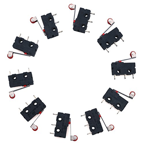
Limit switches are very cheap, so you’ll pay more for shipping than the actual part itself. For example, the cheapest thing on amazon is a 10-piece set ($7)
https://www.amazon.com/URBESTAC-Momentary-Hinge-Roller-Switches/dp/B00MFRMFS6/ref=mp_s_a_1_3
A lot of printers come with a spare, so if you have any friends with a printer, you might ask if they have any spares. Voltage/amperage doesn’t matter, it’s just a small 5V signal line so you won’t blow anything up.
The switch doesn’t even need to look the same as the original, it can be anything. It only matters that it “clicks” at the same spot each time, which all limit switches will do. This switch just tells the printer where the bottom of the print bed is.
The only thing that matters is that you have the same two mounting screw holes (which most of these limit switches have).
The limit switch isn’t axis-specific, meaning you could use the same switch for the X,Y, or Z axis.
When the button clicks, that’s the equivalent of touching the two wires together.
Edit: if you really want to save money, here’s a set for $4.80 https://www.ebay.com/itm/5-pc-TEMCo-Micro-Limit-Switch-Lever-Arm-Subminiature-SPDT-Snap-Action-LOT/191202625167
Edit 2: if you live in the US, go to a local RadioShack. They’re roughly $1-2 there. https://www.radioshack.com/collections/switches/products/spdt-switch-without-roller?variant=20332090693
Wow, thanks! Be sure to post any wands you make to r/wandsmith, we’d love to see them and are there to help!
Another thing I bought was a deadman switch so when you hit the floor, and check your pants lol, the lathe will automatically turn off. Also makes it easier to start and stop to see how things are going without having to mess with switches (depending on your lathe)
You might consider a Deadman Switch if you don’t already have one.
I got this switch for my saw. It's the same manufacturer that grizzly puts on their equipment.
http://www.amazon.com/Woodstock-D4160-110-Volt-Paddle-Switch/dp/B005W17HYY/ref=sr_1_3?ie=UTF8&qid=1417293379&sr=8-3&keywords=woodstock+switch
I used LED tape found off Amazon...super cheap:
https://www.amazon.com/gp/product/B00HSF65MC/ref=oh_aui_detailpage_o01_s00?ie=UTF8&psc=1
I just used 22 gauge wire I got from Home Depot to solder the positive / negative to a 12v power supply. To turn the lights on and off, I just used a cheap limit switch:
https://www.amazon.com/URBESTAC-Momentary-Hinge-Roller-Switches/dp/B00MFRMFS6/ref=sr_1_3?ie=UTF8&qid=1536763141&sr=8-3&keywords=limit+switch
​
I'll try to take some pictures when I get home tonight.
If you can get a good balancing charger and can be responsible and safe with it, a lipo will definitely be better than IMRs as far as performance goes. If you do go with lipos, you should probably get a better rev switch.
Here's a good rev switch:
https://www.amazon.com/SODIAL-Microswitch-V-156-1C25-plunger-action/dp/B00K67YO8G/ref=sr_1_2?ie=UTF8&qid=1496202242&sr=8-2&keywords=15A+microswitch
And here's a great lipo:
https://www.amazon.com/ZIPPY-Compact-1000mAh-Lipo-Pack/dp/B00TDCDKLW/ref=sr_1_1?ie=UTF8&qid=1496202444&sr=8-1&keywords=zippy+compact+1000mah+3s+25c+lipo+pack
Saw a similar issue with mine when I first set it up - switch worked but no lit led.
My issue of course was a wiring problem. For the led to be activated you need to make sure that the additional led connections are made too. This will depend upon the switch you used of course but if you are using something like this https://www.amazon.com/Quentacy-Momentary-Waterproof-Stainless-Suitable/dp/B075QBJVTS?ref_=ast_bbp_dp then check the wiring diagram for program 1. My mistake was I missed that the NO (Normally Open) and the positive LED legs should be shorted to each other. Since mine had a wiring harness I just connected both wires to the positive connection of the zvs unit.
Hope your led issue is a simple fix like mine
BTW I like how you were able to fit it into that compact case, looks cool
Creality 3D Printer Part Limit Switch With Separate Package CNC for RAMPS 1.4 RepRap 3D Printer CR-10 10S,S4 ,S5 (Pack of 3) https://smile.amazon.com/dp/B07BF8KXW3/
Ok so the heat bed is here:
http://www.aliexpress.com/store/product/200X200mm-400W-12V-w-NTC-100K-Thermistor-Keenovo-Silicone-Heater-3D-Printer-Heater-Heatbed-First-Grade/210086_32230108542.html
and the relay is here:
http://www.amazon.com/Amico-Solid-State-SSR-25-24-380V/dp/B0087ZTN08/
(thanks to BillDaCat)
Where is the metal brace thingy? (or is that part of your printer? Or the fiberglass part?)
Information Fire Hose
it's a common arcade button replacement micro switch.
if you dont have a bunch of arcade buttons sitting about and need to order a part to do the mod, get these instead: https://www.amazon.com/gp/aw/d/B00MFRMFS6 . it will make the pedal action not snap so much, and because you don't need so much force you can put it closer to the middle if you like.
the switch is attached to the side with 1" #4-40 screws and nuts... but if you plan to gig or tour it, buy nylon lock nuts for them or the shit will fall off constantly.
the jacks I used are also stereo, and the freeze trigger is on the tip and ring to avoid chassis grounding issues affecting the audio signal path. I just used a normal aux input cable to wire it.
happy soldering :P
(edits, I hate typing on mobile)
https://www.amazon.com/gp/product/B00K67YO8G/ref=ox_sc_act_title_5?ie=UTF8&psc=1&smid=A3G3SQGWUPUX9W is a switch I've seen used. As long as your batteries don't rhyme with schmustfires.
This is the relay board I'm using. I'm going to use two separate arduinos to turn each one on (using "or" logic). I don't have a lot of experience using diodes, what exactly would I use? And do you mean literally I do:
Arduino1->Digital out->diode->Relay input1, then
Arduino2->Digital out->diode->Relay input1
Well my Stryfe has a pair of MTB Rhino motors instead of the stock ones. They're 12v instead of the 6v stock motors, and run on a 3S LiPo battery instead of the four AAs in series it normally takes.
1.5v * 4 = 6v max vs the LiPo at 12.6v max
I made this to help it fit.
Keep in mind that you need to redo the wiring with something thicker to keep from burning it out. And replace the stock trigger switch with something heavier, I think I used one of these.
I put a little voltage meter on connected to the jam door as well, so I know when it's running low.
So basically I've completely replaced all of the electrical components but it sure hits a lot harder now. You can actually get some decent range from it.
If I wanted to mess with it further I'd probably replace the flywheels with something that could grip a bit better, but the problem I ran into messing with it last time was if they grip too hard they shred darts.
Have no fear! You have a simple task ahead of you.
If I was doing this, I would use the following:
This bad little boy can handle 250 VAC at 10 Amps (which is going to be way more than you need). It has 4 relays, so you could control up to 4 drills or other widgets if you needed to. Each relay has a NO (normally open), NC (normally closed), and C (common) Contact.
This little bad boy is how you control that relay. You can write a very simple program on your computer that you put on this device (I am talking like 3 lines of code) that will turn a digital output on for 7 second, then off. Hit the reset button and it does it all over again! The digital output on this board will get a wire stuck over to the input on the Relay board above.
How this all works: Take a simply extension cord (unplugged, obviously) and open up the insulation. There are usually 3 wires in it, black, white, and green (these can vary, so be careful and choose correctly). Take the Black or White wire and cut that bitch. One end of the cut wire can be stuck into the common terminal of the relay board. The other end can be stuck into the NO (normally open) terminal. What this will do is that when the Arduino board sends 5 volts to that relay, it will switch. This will connect the Common and NO terminals together, allowing power to flow through it to the drill. On the drill end I would just zip-tie or rubberband the trigger so it goes on when the relay changes.
CAUTION 120 volts or 220 volts (depending on where you live) can be very dangerous!!! That relay board will have open terminals. Because of this I would HIGHLY RECOMMEND that you put it in some kind of plastic case. I would also run electrical tape over the pins on the underside of the board to make sure you can't zap yourself.
When I get home I can draw you up a wiring diagram if you like and I could give you the basic code you would need.
Good luck!
Didn't take days. Less than an hour, but at the same time I've done about 3-4 of these before so I was already familiar with the inside of a 360 controller.
Here's the tall tactile switches you need for the paddles: http://www.amazon.com/Amico-Momentary-Tactile-Button-Switch/dp/B008420WOA/ref=sr_1_3?ie=UTF8&qid=1394140371&sr=8-3&keywords=tactile+switches
That's 100 of them which is way too many, but only buying 3 or 4 is still only like $1 less...so I bought 100 and they've lasted me through various projects.
You also need (it looks like a lot more than it really is, but I'm being detailed)
You don't really have to adjust voltage. A PWM speed controller can be used for the same purpose (adjusting average voltage) and they're much cheaper. A 10A PWM speed controller can be purchased from Amazon for $11 shipped. Most of them will output in the same voltage you supply.
https://www.amazon.com/RioRand-trade-Upgraded-6V-90V-Controller/dp/B00F839VNQ
Seems as if you have all the parts you would need for a basic build. I'm still a bit new to this myself, so hopefully someone else will correct me if I'm off the mark.
I used the following parts:
I think that's it. I also have a few additional parts for the lighted push button, but you wont need those if you use a regular one. I can always post that info if you need it.
Check the FAQ for tool recommendations for the basics you would need there.
The SX350 allows for gravity changes (by tilting left/right) to control the wattage and uses it for menu navigation so the buttons are only there if you want more direct control.
edit: If your SX350 does not have the buttons pre-wired there are pads for them on the chip you can wire your own. I believe there is a software update to enable them from Yihi. The one I got from Varitube was already set up for them.
Normal momentary buttons are fine. I used something like This but any tactile switch should work fine.
I have some of these on order as they look/feel a bit nicer then the basic plastic ones i have now.
You might want some magnets for the faceplate. I got some 1/8"x1/8" and 1/4"x1/8" rare earth magnets off amazon and epoxied them in. Check the FAQ for some recommendations on glues and such.
I would also recommend heat shrink tubing and some liquid electrical tape for the solder connections.
Hope that helps.
For a display I am using this: i2c 7-segment display, and if you are grabbing the display you can't use the Spark Core relay board because they use the lines that are setup for i2c to control relays instead.
So the total bill of materials for my build is:
I don't believe you can get a local spark cloud server going, but the beauty of it is that you don't have to. You can just use their cloud service for free and be able to read variables and run registered functions securely and remotely without any issues. How I have it set is so that the spark core by default won't control the temp but can be given a command to set the temp and then it will just hold that temp until a new command comes in. So far it has been holding my fermenter to within a degree and switching between temps nice and quickly. I am very pleased, but still want the BrewBlogger integration so I can setup what temp I want at what time and to record and graph the temps. By next week I should be pushing some code up to github, so I'll PM you then and give you a link.
You could easily run BrewBlogger off of a Pi if you didn't have another place to run it, but it's just a PHP website that would need a scheduled task to run to fetch temps.
Currently it's an Arduino running an AD9851 module which is then connected to a pretty shameful homebrew amp. I also have it connected to a cheap relay board. One relay is used to switch power to the amp, the other switches the antenna feed between the amp output and the SDR chain (preamp, Ham It Up, RTL-SDR).
For software I've written some stuff to send RTTY and Morse.
Foot pedal switch from Amazon, my dude.
SainSmart 2-Channel Relay Module https://www.amazon.com/dp/B0057OC6D8/ref=cm_sw_r_cp_apa_i_mgsFDbSR97ZA7
And the pi needs to have the pin initialized as an input / output pin. It must be getting a slight amount of current when just powed on but not initialized?
Nothing directly. You'd need to set up a 2 pole contactor with a 120 volt coil and connect your conventional 120 volt smart switch to that. Since you already didn't know such a thing existed, I highly recommend you call an electrician to install and wire the panel.
One of these - https://www.amazon.com/dp/B001KGSJ74/ref=twister_B07C1X6SHD?_encoding=UTF8&psc=1
​
It uses 120vac to throw the coil for the main load. From the comments, only a tiny fraction is necessary.
"The Actual, Factual, and measured Coil current at 110VAC is .04 amps or about 4 watts.The Coil does not draw .5 amps or 55 watts."
​
Given that Sonoff had issues in 2017 about insufficient solder on the POW power lines, I'm glad I sent mine back.
https://esp8266hints.wordpress.com/2017/03/01/itead-recall/
​
I think there's other Tasmota compatible relays. I'll see if I can dig it up.
​
URBESTAC 250V 5A SPDT 1NO 1NC... https://www.amazon.com/dp/B00MFRMFS6?ref=ppx_pop_mob_ap_share
I just used a spring I had laying around, no idea what the spring constant was. I would recommend a pretty stiff spring.
I must be confused about how switches are rated. This was is listed as a 15A rating. Which should be adequate right? Or maybe you were meaning that for the given size of the switch it could have a higher amp rating?
Hi /u/overlyapologeticguy! /u/bntyhntrqueen made me do this.
I just added this to my wishlist. Why, you might ask? Becuase I want to build an electrical light panel and what good would that be without an awesome EMO switch?
(I also added a master switch to the list but I figure I'm supposed to pick one thing to add to your list. So I went with that.)
This?
https://www.amazon.com/RioRand-trade-Upgraded-6V-90V-Controller/dp/B00F839VNQ
I didn't have a relay picked out yet, I'm kind of in the brain storming stage right now. I came across this board on amazon and thought it might do the trick:
https://www.amazon.ca/SainSmart-101-70-101-4-Channel-Relay-Module/dp/B0057OC5O8/ref=sr_1_21?ie=UTF8&qid=1486504628&sr=8-21&keywords=usb+relay
It says it has a Standard interface that can be controlled directly by microcontroller (Arduino , 8051, AVR, PIC, DSP, ARM, ARM, MSP431, TTL logic)
Maybe i'll give it a go.
Hey man. I'm happy to answer any questions you have. I took some more pics but not sure what you're after, so I'll just be detailed .
This Switch is the exact switch I bought
another switch pic
Crappy subs I've had for a decade, the 650w amp just as long, but it still pounds!
Because mobile phone... I posted and kind of explained these backwards I've realized. It's worth mentioning that you start wiring from the front and run it to the back. You need to drop wire from under the hood into behind the glove box. If you started from the trunk you won't be able to push the wire where I did.
You can see where I mounted the line out converter above the sub. And also that the stock Infinity 10 speaker system is still in tact and unaffected by this install. The 8 inch sub is still there.
Front of sub
Here you can see the wiring from front of the car coming into the trunk all hidden. Standard stuff here, around the back seat, under the rear panel, under the scuff panel (where it says Genesis at the door sil), up the panel behind the glove box and into the front of the car (see next picture).
Back of sub
I mounted the fuse holder to the fuse box panel (Genius!) and fed the 4g 12v wire through the grommet in the pic. I had to remove the hard plastic cover and cut a slit in the soft rubber water barrier inside, then drill a hole big enough in the hard plastic outer cover. Feed all of the wire through there and eventually to the trunk. I also drilled a hole near the side of the + batter terminal cover to make a notch for the thick 4g wire to fit.
wiring
Let me know if you wanted to know anything else.
I also posted a while ago about the backup camera installI did which is a nice addition for those who don't have it.
Edit: Added link to other post
https://www.amazon.com/API-ELE-Momentary-Waterproof-Stainless-Self-Reset/dp/B079GNNSRP/ref=mp_s_a_1_2?ie=UTF8&qid=1541366661&sr=8-2-spons&pi=AC_SX236_SY340_QL65&keywords=waterproof+push+switch&psc=1
https://www.amazon.com/Quentacy-Momentary-Waterproof-Stainless-Suitable/dp/B075QBJVTS/ref=mp_s_a_1_16?ie=UTF8&qid=1541366661&sr=8-16&pi=AC_SX236_SY340_QL65&keywords=waterproof+push+switch&dpPl=1&dpID=410iuxGxhhL&ref=plSrch
https://www.amazon.com/TOTOT-Automatic-Self-Reset-Waterproof-Dustproof/dp/B07C4T6XT5/ref=mp_s_a_1_19?ie=UTF8&qid=1541366780&sr=8-19&pi=AC_SX236_SY340_QL65&keywords=waterproof+push+switch&dpPl=1&dpID=41UbL7CKvtL&ref=plSrch
You're going to be looking for something like this.
https://www.amazon.com/dp/B07BF8KXW3/ref=cm_sw_r_cp_apa_i_Mhv4CbV5G6G18
I would replace your discrete components with an Arduino Pro Mini. You can connect three output pins to some relays, and drive the LEDs with a 5V power supply. You'll probably want to put a resistor in series with each LED, instead of one resistor for the whole string, to minimize risk of damaging them: (5V-3.4V)/.025A = 64Ohms, so use somewhere between 50 and 75 Ohms for each LED. Alternatively, you could run the whole thing on 3.3V and skip the resistors, but those power supplies aren't so common. In that case you'd want the 3.3V Arduino. PM me if you need help programming the Arduino, it's pretty easy.
Why not just wire up one of these to the button instead?
https://smile.amazon.com/dp/B008ZY9CXE
I'd hate to have a saw start spinning if I leaned over the table and hit the pedal accidentally, or at any point really.
I use a paddle switch like this:
https://www.amazon.com/Woodstock-D4151-220-Volt-Paddle-Switch/dp/B005W17FRS
https://www.amazon.com/Woodstock-D4160-110-Volt-Paddle-Switch/dp/B005W17HYY
With leads or sockets made for removable tools:
https://www.amazon.com/Router-Safety-Paddle-Switch-Removable/dp/B01B1KE4EK/http://www.rockler.com/safety-power-tool-switch
http://www.woodpeck.com/elecswitch.html
https://www.amazon.com/ROUTER-TABLE-PADDLE-PEACHTREE-WOODWORKING/dp/B00153I3IC
I'm not clear what you mean by I/O board? If it's just the gpio header on the pi itself, it's 3.3v but at 10mA, maybe 12mA? Enough to drive a signal, but not enough to energize a coil. (If you do have a separate board, you'd have to either lookup the specs for it, or let us know which one so we can figure it out.)
So you'll need something to use that to push a relay. Typically a darlington pair, an optoisolator, or a trip to Amazon.
I'm cheap and lazy, so I regularly use either these, which are 3v modules, or these which are awesome, but do need 5v drivers (I usually use an MCP23018 between the pi & the relay board - you'll find a shedload of documentation for this on the googles, but I'll shout-out adafruit's docs specifically). For the sainsmart ones, when they say 12V, they mean you'll need a separate 12V supply to push the relays themselves, they're not expecting 12V from the pi.
These will get the pi to drive n/c & n/o dry contacts you're used to, but I note you also asked about triggers - relay boards won't help protect inputs, so be warned that the inputs are also 3.3v and have very little tolerance (5v will kill them, let alone 24V. Anything you put in the IO lines goes straight into the CPU, so be gentle).
A couple of projects you might want to look into if you want to let someone else worry about the interfaces;
Parts list is dependent on what controller you use. This is a decent one.
https://www.amazon.com/dp/B0195V53X8/ref=cm_sw_r_cp_awdb_t1_n5DWCbX7WY6NB
You will need a box or container for the pid and wires. A temp probe that will work in the 500c temps. And a solid state relay. https://www.amazon.com/uxcell-Solid-SSR-25-3-2-32V-24-380V/dp/B0087ZTN08/ref=pd_aw_fbt_328_3/147-7782181-2201822?_encoding=UTF8&pd_rd_i=B0087ZTN08&pd_rd_r=0b211574-6776-11e9-b475-c358acaaf9b4&pd_rd_w=As9SE&pd_rd_wg=uOeRp&pf_rd_p=3ecc74bd-d08f-44bd-96f3-d0c2b89f563a&pf_rd_r=X57XWHY664NJBVVBD0AS&psc=1&refRID=X57XWHY664NJBVVBD0AS&th=1
That's an example, I need to do more digging to make sure its capacity is ok. I think it should work.
In general, a pid controller says "turn on the relay when the temperature is between x and y. Turn off when the temperature reads z.
This type of probe would work
https://www.amazon.com/Perfect-Prime-TL1815-HeadProbe-Thermocouple-Temperature/dp/B0142S9J4S/ref=pd_aw_sbs_79_1/147-7782181-2201822?_encoding=UTF8&pd_rd_i=B0142S9J4S&pd_rd_r=49d6e55b-6777-11e9-af2b-df456cd2a423&pd_rd_w=eR1mx&pd_rd_wg=w1VKC&pf_rd_p=aae79475-6dc9-4a12-80e8-27b63108fa72&pf_rd_r=BHRC8SSGY71B2D18D2Q1&psc=1&refRID=BHRC8SSGY71B2D18D2Q1&th=1
Non-mobile: Here's a relay
^That's ^why ^I'm ^here, ^I ^don't ^judge ^you. ^PM ^/u/xl0 ^if ^I'm ^causing ^any ^trouble. ^WUT?
I have old (like 50s/60's old) craftsman bandsaw and table saw that someone had rigged light switches on for power at some point, I replaced them with these paddle switches and I love them.
https://www.amazon.com/gp/product/B005W17HYY/
They are kind of bulky so you need a place to put a surface mount electrical box, but other than that they're a pretty simple install using basic crimp-on spade connectors.
Also since you'd put the switch in-line with the cord you could put a longer power cord on it while you're at it, if you're already dealing with a short cord.
When I get home tonight I can snap a couple pics of how I have them installed if it would help.
Don't. Use something like these.
I'm sure you could find them cheaper on Aliexpress or eBay, but I use these exact ones with NodeMCUs, WeMos D1 Minis, and WeMos D1 Mini Lites all the time. They work great.
For safe shut downs, charging warnings, and charging status - Adafruit PowerBoost 1000 Charger - Rechargeable 5V Lipo USB Boost @ 1A - 1000C-Purchased from amazon, https://www.amazon.com/gp/product/B01BMRBTH2/ref=ppx_yo_dt_b_asin_title_o08_s00?ie=UTF8&psc=1
Shell used-Gametown® Full Housing Shell Cover Case Pack with Screwdriver for Nintendo Gameboy Classic/Original GB DMG-01 Repair Part-White (pick whatever color you want)-Purchased from amazon, https://www.amazon.com/gp/product/B01K1C2L1C/ref=ppx_yo_dt_b_asin_title_o06_s00?ie=UTF8&psc=1
Screen used- BW 3.5 Inch TFT LCD Monitor For Car/Automobile – purchased from amazon, https://www.amazon.com/gp/product/B0045IIZKU/ref=ppx_yo_dt_b_asin_title_o09_s00?ie=UTF8&psc=1 (side note here is that in order to make this fit nicer, I installed it upside down in the case.
Speak used - uxcell 16pcs 27mm External Magnetic Speaker Loudspeaker 8 Ohm 0.25W, purchased from amazon, https://www.amazon.com/gp/product/B010V4RAAW/ref=ppx_yo_dt_b_asin_title_o04_s00?ie=UTF8&psc=1 (do not put ANYTHING on the top of the speaker when you install or it will not work.
Prototyping bread board, I purchased from amazon but it is no longer available at the link.
I used this PCB for the buttons on 1 build, the drill guide is VERY useful for this project. - 4 Button PCB For Gameboy DMG-01DIY Pi Zero Made In USA With Grounds and Hole Guide BY:Atomic Market, purchased at amazon, https://www.amazon.com/gp/product/B01JKJCQVM/ref=ppx_yo_dt_b_asin_title_o07_s00?ie=UTF8&psc=1
L-R buttons- 100 Pcs 6 x 6mm x 9.5mm PCB Momentary Tactile Tact Push Button Switch 4 Pin DIP, purchased at amazon https://www.amazon.com/gp/product/B008420WOA/ref=ppx_yo_dt_b_asin_title_o08_s00?ie=UTF8&psc=1
28 Gauge Wire - Ribbon Cable - 10 Wire (15ft), purchased at amazon, https://www.amazon.com/gp/product/B007R9SQQM/ref=ppx_yo_dt_b_asin_title_o09_s00?ie=UTF8&psc=1 (I recommend going to a smaller (higher) gauge than 28. 30 or 32 would have made it a lot easer but 28 will do.
Indicator lights, Uxcell a11092800ux0119 Uxcell (Pack of 75), purchased at amazon, https://www.amazon.com/gp/product/B01F0TCXSW/ref=ppx_yo_dt_b_asin_title_o03_s00?ie=UTF8&psc=1 (these are totally optional)
Resistors and capicitors (audio), purchased from https://www.taydaelectronics.com Note: heres the guide I used for the audio too! https://sudomod.com/forum/viewtopic.php?t=480
Old Gameboy game cartridge. For aesthetics.
Headphone jack, ebay, https://www.ebay.com/itm/3-5mm-Stereo-Female-Socket-Audio-Jack-5Pin-PCB-Panel-Mount-Connector-PJ325-/400959590673
Volume wheel, ebay, https://www.ebay.com/itm/20pcs-B103-16x2mm-10K-Ohm-Double-Dial-Taper-Volume-Wheel-Duplex-PotentiometerBS/293146992835?epid=11009192051&_trkparms=ispr%3D1&hash=item4440ec20c3:g:NZkAAOSw3h1ZUavq&enc=AQAEAAAB0BPxNw%2BVj6nta7CKEs3N0qUCHDbWKwW7sKftQNu9OoIx7SAZoMMNoO7ZC%2BQU2m6tHizIeixg2Hdk8yQin%2B7yNcIdtTzT%2FneqdaLt1WntvDDMDNnZ9%2BCyBsPWRiKLCNPKdeaaZNnBjMoVA%2F0tK%2BtG7DVLtcUKV1a4ZUD8%2F3Lgu9eesPLoBiXZs77Vo7R%2FDaZVMV%2FquPTyLO%2FBFipuEkim1t7BIMiLOi2P3Z31r4yxIdLUw6SCVesvVeqBQuoKov776Dxzk8pUY7PZvu4Q3ULnqBWmlWXsKXc8iAp9juNxUBFHnDgW6A7iElTGYe0sQRXfFHW73jI62f5aO%2FnqGANNK%2F7KJlu474aR3Gae9%2FJCT%2FwoLqmBb4FfizrUJ6qKEuVeLAi31kJSoJXIv4msi3r0bMNSm2D7FL5DUBr0Bc4xsSPi7KFWI9AhmQjUn%2FsLVysgEKd8QEildi1DULaVOX11bv95PGoXvfAusYXSi5NQZk4oZJHr6QIjXu5w4e9Nd2lFtmG4ZB%2BkqROOwwliad72iafj6cbSLphBAjtWGZQVNbmcdKXG6S8h7cTVqt0aD4oej7%2BlDVihmo%2BV0Rc2MhA9FgkM%2BcyzPd0qc9vHvdxjpQUq&checksum=2931469928353c744c25da8843a496116014d4766745
Micro SD card (16 GB minimum)
Female Micro usb Port, (I know I did buy these but I can’t find the link. I bought female micro usb ports to make charging easier.)
I want to say this is the battery that I used, specifically because after taking the shell off it was the perfect fit inside of a gutted Gameboy Game cartridge-https://www.bestbuy.com/site/mycharge-razorplus-4000mah-portable-charger-for-most-usb-enabled-devices-silver/6292246.p?skuId=6292246
3d printed button wells-http://market.sudomod.com/3d-printed-gbz-button-wells/
Extra buttons-https://www.retromodding.com/collections/gameboy
Screw bracket-http://market.sudomod.com/3d-printed-gbz-screw-bracket/
I got A LOT of buttons, glass screen shields, the other three builds button PCBs, some stickers, seriously a lot of stuff from https://store.kitsch-bent.com/ his store is unfortunately closed as he has had life catch up to him and has some shit to attend to. If he comes back online show him some love.
Stuff I got from kitsch
PCB board with LR input points
Buttons for X/Y (you can opt to just get replacement snes or an extra set of Gameboy buttons.
Glass screen that fit the GB shell after removing extra plastic
And obviously you should have a pi zero/w as well a shit ton of patience.
Well if you must know, Its a cremation box, usually sold for $20-30 on ebay. The Heating module and coil costed 13.00 from https://www.amazon.com/gp/product/B01GDVVANA/ref=ppx_yo_dt_b_asin_title_o05_s01?ie=UTF8&psc=1 The Button costed me 9.99 here https://www.amazon.com/gp/product/B075QBJVTS/ref=ppx_yo_dt_b_asin_title_o05_s01?ie=UTF8&psc=1 and the power supply costed me 11.11 https://www.amazon.com/gp/product/B07NR6FPN9/ref=ppx_yo_dt_b_asin_title_o05_s00?ie=UTF8&psc=1
With shipping and Best offer accepted, i think im doing justice here. These were the best prices i could find at the time from MULTIPLE vendors. I have a Portside Mini in the mailbox tomorrow and THIS box has NEVER failed me in the last few months since built. It is a work in progress yes. It can be expanded and definitely worked on to make it much better. I would of taken $50 which is what they USUALLY sell for but i started it at 75.00. Im sure it will cost me about 7-10 to ship when wrapped properly. Not loony at all.
The relay setup and wiring is not hard but it can be a bit confusing at first until you figure out the GPIO wiring and setup. With my setup I can control a power strip that the Pi (via Octoprint menu entry) can turn on or off via the relay as well as having LED lighting inside my enclosure controlled that can also be controlled from Octoprint. If you want to give it a go just pick up a relay and some connectors to wire it to the GPIO pins. Feel free to hit me up once you have the hardware and I can share my wiring and Pi GPIO config with you so you can get going quickly. I like the 4 channel relays since they are only a few bucks more than the 1 or 2 chan versions and it allows you to add devices in the future. They are under $10: https://www.amazon.com/gp/product/B0057OC5O8/ref=oh_aui_search_detailpage?ie=UTF8&psc=1
Yeah, the arduino can supply only a couple mA from each IO pin, that pump likely needs 500-1000mA to run.
You can also use a relay for a more simple setup, like this board for example, it will let the arduino switch high current loads like the pump easily.
Here's one that would work: https://www.amazon.com/gp/product/B001KGSJ74
See my other post for more detailed instructions.
Thanks for the detailed write-up on your safety mods!!
I've seen Solid State relays recommended over/instead of the MOSFETs you linked to. e.g. something like this but rated at 25A.
However I'm having trouble deciding which one on Amazon is compatible. Would I need one that is DC to AC or DC to DC?
Like would this one be appropriate? Or this one?
I'm looking at Amazon only because they ship from the US and I'm hoping to have a Mosfet or SSR in hand by next week.
EDIT: Doing some more research, it seems like one of these is what I need? Amazon results for SSR-40DD The recommended brands are Fotek, Auber and Crydom.
Nice to hear. what do you think is going bad in the relays? Some of the lighting is actually on some heavy duty relays. The relays that power the 120 are actually powered by 120 themselves, Something like this Those relays obviously would last a lifetime for a small load around 15 amps. Pretty cheep solution with a little more work to have a z-wave relay control another relay but if It makes it last longer lol.
Edit: whats your set up like? What components are you using?
Just need yourself a deadman switch and you're set! I have one of these for my proxxon, so much more productive to just hit a pedal and you're ready to rock.
MLCS 9080 Billy Pedal Foot Switch, Deadman Style https://www.amazon.com/dp/B000LJNJOE/ref=cm_sw_r_cp_apa_i_L-AxDb30R8P11
I have been using an all-in-one Sainsmart Relay to control my garage door via the Pi.
what about this? https://www.amazon.com/SODIAL-Microswitch-V-156-1C25-plunger-action/dp/B00K67YO8G
I considered that and opened up my piano to see how much effort that would take, but I found that because it's an upright and due to how the strings are positioned some of them are not at all easily accessible. :( On the bright side, I found these which will serve my purpose; now I just need to figure out how to control this from a raspberry pi. Thanks for the suggestion however!
Wow Thanks for the descriptive response!
I'm not very great at electronics, but here is the exact switch I'm using.
As for power source, I'm probably going to use 110 VAC to power the 4 ch relay board. http://www.amazon.com/SainSmart-101-70-101-4-Channel-Relay-Module/dp/B0057OC5O8
This is the solenoid I will be using
Thanks! Your post really helped me think it through. Just need to put it to work lol.
That's helpful. The relays are rated 10A t0 12A so the current is less than I'd assumed. I mean it should be less than the rating of the relay... big assumption, perhaps. It puts the current in the range of some low voltage PWM speed controllers sold on Amazon. My concern is the lower voltage is 6V and you need it to run down to 5-5.5V will it work? https://www.amazon.com/RioRandTM-Upgraded-6V-90V-Motor-Controller/dp/B00F839VNQ Better than a resistor if i works, depends on how much of a project you want to make of it.
A cable tie is pretty reversible. A foot-operated dead man switch would help, safety-wise, something like this...
http://www.amazon.com/MLCS-9080-Billy-Switch-Deadman/dp/B000LJNJOE/
Not much to see yet. So far it is an R-pi, a few DHT11, a relay module, one (or maybe more) cheap PIR motion detectors, and a toggle switch.
I'm using Monkey webserver, and playing with some cgi scripting. I started piddling with HTML5, and I want to try to make it as nice as I can, but I am not a web developer, so I am having to slog through some of this. If it goes well, I might make a post in here or in /r/HomeAutomation
Here's the relays I used. The reviews have some good documentation on current requirements and such. I ran 12V to the Vin of the relay boards, as well as to the common terminal of all 32 relays (since the goal was to supply 12V to an ematch when the cue was triggered). The positive end of the cue terminals were connected to the NO terminals of the relays. This means that normally, the ematches are disconnected. When a relay is triggered (by setting an Arduino pin to ground, thus triggering one of the active low relays on the board), the match on that relay is connected to the 12V source. Since the negative terminals on the channels are already grounded, boom.
E-match will detonate with around .5A of current, though most people recommend 1A per match to be sure. This is how we determine how many matches can be fired from one cue; we divide our 12V source by the resistance of all of our matches in series (typically around 2 ohms each) and ensure we can still supply 1A of current. Once the matches detonate, the circuit is broken. Does that clarify things?
https://www.amazon.com/MLCS-9080-Billy-Switch-Deadman/dp/B000LJNJOE/ref=pd_sim_328_8?_encoding=UTF8&pd_rd_i=B000LJNJOE&pd_rd_r=TJS35078VTZT2MM39N06&pd_rd_w=jg3Wa&pd_rd_wg=1byKr&psc=1&refRID=TJS35078VTZT2MM39N06
this is the one I have, it's 15 amp
This.
I got one of these recently and it seems to work fine. Fairly cheap, super easy to use.
Take a look at using a contactor with a smaller relay to act as as a "bridge" to a MCU.
In other words (assuming you're working with two 120V "hot" legs and a neutral - verify this!):
https://imgur.com/fEHNtIr
You might want to use a 5V relay board to make it easier to wire.
Just make sure that you mount all the components in a safe enclosure (~$25 on Amazon).
Sure. Here's the contactor:
https://www.amazon.com/Packard-C230B-Pole-Contactor-Voltage/dp/B001KGSJ74/ref=sr_1_2?crid=OIUJ07IZNPPX&keywords=30+amp+contactor+120v+coil&qid=1550624331&s=gateway&sprefix=30+amp+contact%2Caps%2C210&sr=8-2
And here's the box I used:
https://www.homedepot.com/p/GE-60-Amp-240-Volt-Non-Fuse-Metallic-AC-Disconnect-TFN60RCP/100674085
It's an AC disconnect box but I just removed the disconnect switch and drilled a couple of holes to mount the relay. The ground bar is useful. Use 10awg romex for wiring it. I also used an inexpensive ($12) internet connected smart light switch that's compatible with google home and alexa to actuate the relay coil. Total cost around $30.
You dont. At least not directly without killing the board. That said there are ready to go relay boards you can order if you want a simple solution, or go read the other comment about using a transistor, he/she is dead on on how to do it.
That said, a transistor is kinda like a relay. Perhaps that's all you need if you are running a small device like a few LED's or something else small.
Ok so looking into SSR's a little more I think I found one I can use. would this be what I want to use to turn on and off the 100W ceramic heating element and the fogger?
I was thinking this for relays, but wanted something smaller.
I plan on switching at least 14 turnouts, which would require two of the boards shown above.
Mosfets are definitely where I'm going now.
Exactly, yes! Everything that requires precise timings, instant response, and/or 5 volt logic would be on the Arduino and the Pi would just handle user interactions.
You could just get an Arduino Uno 3, that's kind of the standard Arduino board especially for people just learning. I just prefer the Mega because it is beefier and has way more GPIO pins. But the Uno 3 has enough to run three relays and your IR sensor easily (which has both 3.3 V and 5 V logic, meaning it can work with the Pi and Arduino respectively).
Speaking of relays, I really like the SainSmart ones and have never had an issue with them. This four-relay module is only $10:
https://www.amazon.com/SainSmart-101-70-101-4-Channel-Relay-Module/dp/B0057OC5O8/ref=asc_df_B0057OC5O8/
Only thing is, and you might know this already, these things are pull-down rather than up. Meaning instead of pushing a 5V signal straight from a digital GPIO pin on the Arduino straight to the relay, you have to use a transistor to basically invert the signal. When the Arduino activates the transistor, it allows the pin on the relay board to go to ground which turns it on. Also, don't forget to always wire so the power off side is your closed side for all valves and such! The last thing you want if a board dies is to have the relay that controls your solenoid valve to default to power on, dumping all your liquid!
It definitely is overwhelming at first, but once you get really confident it opens up a whole new world of fun engineering!
Awesome man. I cannot tell you how cool I find all this. Science!
Here is what I have purchased so far.
12v 6a 72w power supply
ZVS Heater and Coil Combo
Switch. Can hold up to 20amps not sure that mattters whatever, room for extra isn't bad.
[Glass Tube]I DELETED THIS AS WHAT I HAD HERE IS TOO BIG! DO NOT BUY THE GUITAR SLIDE I HAD LISTED! NEW TUBE. I ordered this from China on a Thursday, let's see how long it takes to get here.
So, I would just be missing the mosfet and momentary switches that you have. Do you find them necessary? I might just buy the mosfet and momentary for peace of mind, but I did see a couple build that avoided the mosfet for simplicity's sake. This build seems to have avoided one.
Any further advice (wire gauge, soldering tips, etc)? I am currently looking for a good box to put it all in. Thanks again for the reply.
EDIT - MOSFET
Momentary Buttons
Mounting things for the momentary buttons
IF ANYONE IS READING THIS IN THE FUTURE, CONSIDER USING A 120W POWER SUPPLY. I DO NOT REALLY UNDERSTAND BUT SUPPOSEDLY IT MATTERS.
Hmm, I guess it does not. Sorry about that. I did a little more searching and found https://www.amazon.com/dp/B07BF8KXW3/ref=cm_sw_r_cp_api_i_-1e4CbGSD477R this one had some comments that people used it on an ender 3. Doesn’t come with cables though :(
I ended up buying this relay module so I can actually switch both the lamp and the printer from the Pi.
From what I can tell its rated 5v but can't find anything about running it at a different voltage. This is the relay I have Link. I just tested it with 12v instead and it works with that as well but at the moment it is working again on 5v as well and I can't tell if it will make a difference with the higher voltage.
Yeah, I have ordered the resistors and breadboard, and will not repeat the 3v to 5v "solution" again.
But I'm curious where the failure is, exactly. Inside one of the components?
There's no documentation with the SainSmart 16 relay board, so I don't know if there are snubbers on the coils, but I'd be surprised if there were.
The opto-isolators are in place, so I wouldn't think the logic circuitry would be jeopardized by surges from deactivated coils.
I don't think Kite specifies a type of button. These will work though: https://www.amazon.com/9-5mm-Momentary-Tactile-Button-Switch/dp/B008420WOA
Yeah, if you're not very experienced in electronics better stay with something already tested, specially for anything mains related!. Probably you could use one of these arduino relay boards, they're fairly cheap and are opto isolated to keep things safe.
That timer switch is not large enough to be capable of running that pump. It will fail quickly and void the warranty.
A contactor is your solution.
Haven't built van yet, but for both my current car and truck I have a little garmin like this that has no monthly fees or anything and all it does is GPS, using free google maps.
The benefit to me is that I absolutely do not want touch-screen controls in a car for AC and things like that, it's just another thing to go wrong, and I mount it right here (sorry too lazy to go take a pic to I drew it) where it's invisible to anyone looking at the car due to tinted side windows to the darkest legal limit. I do not have to connect/disconnect my phone, I don't need a little cradle taking up my windshield, and I can glance over at it just fine. I have one mounted in the "top" glove box of my tundra as well and that one is super hidden. I did it first so I even put a cheap microswitch on the door that turns on the device when it opens.
If they ever break, who cares? Buy a new one they are dirt cheap. No fiddling with phones, nothing sitting on the dash, and concealing it I think might help against people breaking in. Even though they are only like $50, there's bound to be someone out there who thinks they are more valuable or would break the glass for $50.
This motor controller!
Using your Arduino you can wire a relay and control it from your phone or computer
The board I bought is a 12v (since the solenoids are 12v), here's a link to it: SainSmart 16-Channel Relay Module https://www.amazon.com/dp/B0057OC66U/ref=cm_sw_r_awd_FCvSub144A8GM
They can be bought cheep, on amazon. You COULD look for just the switch (Looks like a KW11 style microswitch) if you wanted to but you would have to be comfortable with soldering/desoldering to install it.
Might be worth getting the 3 pack linked above as the lever you replaced probably wont last on the switch so it would be better to replace both now and have a spare.
I decided to do PWM. If I use a transistor I won't need a heat sink, right? Will I need any capacitors?
these are the parts I've found so far (Other than motion sensors, short jumper wires, and other common items)
Transistor \
Relays/ One or the other, transistors preferably
Wires
Nano Every
Breadboard(s)
Barrel Jack
Soldering Iron
Solder
Lights + Cable - Would the cable work with the barrel jack to provide power for the Nano Every and the LEDs?
Potentiometers
Try homing the X axis. And before it finishes homing, press the limit switch (looks like https://www.amazon.com/Creality-3D-Printer-Separate-Package/dp/B07BF8KXW3). It should stop immediately since pressing that switch tells the board that the X has hit the end. If it stops, then the carriage might not be hitting the switch. If it doesn't stop, then check your wires first and then try using the switch from the Y or Z axis instead to see if it's a board, cable, or switch issue.
Those should work fine, but just for neatness is probably go for this 4 in 1 relay board https://www.amazon.com/dp/B01HEQF5HU/
First of all I'd connect just the relay board to the Arduino and check it still works with your sketch, you should hear it click on and off when the LEDs should work.
Then sort out wiring your strip.
I believe this one? https://www.amazon.com/Creality-3D-Printer-Separate-Package/dp/B07BF8KXW3
https://www.amazon.com/DROK-Regulator-Controller-Temperature-Governor/dp/B00BXUCWQG/ref=pd_day0_60_1?_encoding=UTF8&pd_rd_i=B00BXUCWQG&pd_rd_r=RHDVTMHJAVMYQ4SCW7R1&pd_rd_w=bCbon&pd_rd_wg=JacZ0&psc=1&refRID=RHDVTMHJAVMYQ4SCW7R1
There's another. $20 ish.
There's not much to it, depending on the relay you have.
Relay's have two parts, a coil and one or more sets of contacts. The coil is what controls the contacts. The coil is an electromagnet, and the contacts are reed switches. When the coil is energized, it causes the reed switches to engage. So by using the contacts as part of a circuit, you can make or break the circuit by engaging the relay.
Relay coils by themselves pull too much current to safely run one with a raspberry pi, so you'll most likely need a transistor to control the relay (a transistor can act more or less like a tiny relay with no moving parts).
If you've bought a pre-packaged relay board (such as one like this) then they've taken care of the transistor for you and all you have to do is hook VCC to the pi's 5V pin, the ground to the pi's ground, and the input you want to control on the board to the output on the raspberry pi.
There are plenty of tutorials out there that show you how to use python to control the pins.
On these particular relays, there are three terminals for the contacts, NO (normally open), common, and NC (normally closed). To switch a circuit you connect one wire to common (usually the middle terminal) and the other wire to either NO or NC depending on if you want the circuit to be On (NC) or Off (NO) when the coil is de-energized. Don't connect a wire to NO and the other to NC and expect anything to happen, they're not connected together. One wire must go to Common for there to be a complete circuit. You are free to connect to all three and switch your common line between two different circuits (one for NO and one for NC)
I can lend you 2 of these:
https://www.amazon.com/SainSmart-101-70-103-16-Channel-Relay-Module/dp/B0057OC66U/ref=sr_1_6?ie=UTF8&qid=1501860037&sr=8-6&keywords=sainsmart+relay
You want one of these (or something similar).
The coil connections go to the switched power coming from your smart switch - one to the phase, one to neutral.
Each phase wire (I think US colours are normally red and black, don't touch the earth) should go through the contacts.
Edited to remove BBCode...
Something like this should work. Just don't turn it past 60% or so.
The 120V part is the easiest and the most dangerous, so pay attention to it. A relay module like this acts like an SPDT switch ("changeover/three way switch") - or more like 4 of them. The light are wired up to the relays just like you'd wire up an ordinary room light to a switch.
The arduino just connects to the little pin header on the bottom and is completely isolated from the high voltage.
r/Arduino will be able to help you write the code (you'll only need the basics for this). IDK why the post was nuked, but you can make a new one asking about the optocoupler tapping of the speaker - it will require a bit of poking around to get an idea what sort of thing is going on in the speaker wires.
SSRs aren't hard to wire up and are a lot cheaper. I bought 20 of them on ebay for ~$20. If it's 12 V relays work well too. Amazon has a card that can control 16 relays for $40.
If you can solder make a scuf tbh
I am an electronics refurbisher and I have had scuf like products come in before and a lot of the time they end up being a controller with some holes drilled in it with paddles and a board you can find online for like 15$ and do yourself
https://www.amazon.com/Playstation-Dualshock-Board-Remap-Install-4/dp/B00SVHWMEQ
https://www.amazon.com/gp/aw/d/B008420WOA/ref=pd_aw_sim_63_1?ie=UTF8&psc=1&refRID=JAERDCKTZASCC1X42QMP
So one like this or this work? Whats the difference between the two?
The switch will be connected directly to the pi's GPIO, which will control a relay. The electrical wiring in the walls will be connected to that relay which is connected to the light. I'll be using a 2 channel relay, something similar to the link below. There are also 8 channel relays, so you can control 8 devices with only 1 Pi. I plan on using an 8 channel relay for a Pi controlled thermostat. Also, prices are much cheaper on eBay if you're willing to wait a few weeks for shipping.
http://www.amazon.com/SainSmart-2-CH-2-Channel-Relay-Module/dp/B0057OC6D8
But yes that would also work if you want to wirelessly control the relay, you just have to be connected to your WiFi.
my idea would be to just drill some holes into the existing plastic-covers and install something like this or this
chances of getting a oem Kia switch/button will be hard, since the switches will be sold as spare parts, thus already labeled.
Something like this I would think, you will just need to search out one rated for your voltage req. RioRand™ Upgraded 6V-90V 15A DC Motor Pump Speed Controller https://www.amazon.com/dp/B00F839VNQ/ref=cm_sw_r_cp_apa_i_TuI3Db0B6842P
!!!
You can control any AC load within reason using a relay module. For example: http://www.amazon.com/SainSmart-2-Channel-Relay-Module-Arduino/dp/B0057OC6D8/
As for temperature control, you should look in to using PID.
Hi Shadow, thanks for the response, the relay I'm using is this one from Amazon.
I connected the relay to the 5V power rail that's hooked up to the Arduino. The ground for the relay is connected to the ground of the Arduino. The signal wires are directly hooked up to the Arduino digital outputs (5,6,7). I have a photo of the circuit, but I must admit it's not the best picture.
http://i.imgur.com/tDr0nTw.jpg
Another thing I noticed, was that this occurred even when I disconnected the Arduino and just ran a 12V source through the component, it was worse when it was connected to the Arduino.
If you are having trouble with z-wave signal maybe wifi would be better. Hook up a sonoff to a contactor. You could do it for less than $20.
https://imgur.com/a/q00X4SF
https://www.itead.cc/smart-home/sonoff-wifi-wireless-switch.html
https://www.amazon.com/Packard-C230B-Pole-Contactor-Voltage/dp/B001KGSJ74
I use this one from amazon. It has a 120v coil so it is easier to control. I use a contactor the pool pump and one for the pool cleaner pump controlled with a dual relay z wave micro switch. But any z wave switch that you can mount will work. Many pool pump panels have a place for a switch to mount. Mine is inside the panel and works great.
You're right, sorry. I am using the magnetic contact that came with Charlie's block, attached to the collet.
I'm not using an Arduino shield, but separate discrete drivers.
I appreciate the info on the pull-up/down resistor and the low pass filter but I'll be honest and tell you that you're speaking above my level of electronics knowledge. I'll do some reading on those topics and see if I can figure out what needs to be tried in those areas.
Do you think the optoisolator relay board will help? These are the ones I bought. I plan to have them actuated with a discrete power supply to isolate the Uno from the spindle as much as possible.
using this: https://www.amazon.com/gp/product/B00F839VNQ/ref=ox_sc_act_title_1?smid=A298K45OP416LP&psc=1 between the input and the relays would work?
I like the simplicity of the resistor idea but It's hard to tell how hot its going to get or what speed a particular ohm value is going to reduce it to until its all said and done.
> How did you have the relay connected to the GPIO?
Through this board, which seems to be properly (opto) isolated.
> how were you powering the whole setup?
USB of the Raspberry Pi to a wall wart.
> sounds like latch-up
If you still think it could be a latch-up (given the board I'm using), how would you recommend preventing it?
The hoist shares the ground and one of legs that powers the motor also powers the arduino. Ill try and sketch up a circuit quick. The relays I am using are [these] (https://www.amazon.com/gp/product/B0057OC66U/ref=oh_aui_search_detailpage?ie=UTF8&psc=1) which as far as I can tell have diodes and are optically isolated.
I tried my first project controlling a high power and current fan and it went great, until it didn't.
Basically I hooked up an Arduino Nano to control a 5v relay that controls a high power relay/contactor. The contactor controlled a 120VAC 15A fan, and turned it on or off when a window was open or closed. It worked perfectly and I called it a night.
Next morning I found that the magnetic sensor fell off the window (sending the "Turn the fan on" signal) and the fan was on as expected. But when the sensor was reinstalled the fan remained on when it shouldnt have. Even resetting the arduino did not interrupt the current to the fan.
This lead me to believe that the 5v relay has failed in the ON position, because this is the only way the contactor and fan would still have power.
Can anyone suggest a more reliable 5v input relay that can provide power to the electromagnet inside the contactor? I've looked at SSRs as being more reliable, and https://www.digikey.ca/product-detail/en/ixys-integrated-circuits-division/CPC1706Y/CPC1706Y-ND/3077519 is one that I think is appropriate, any other suggestions?
5v relay
(https://www.amazon.ca/gp/product/B073HX1DK2/ref=ppx_yo_dt_b_asin_title_o00_s00?ie=UTF8&psc=1)
Contactor
(https://www.amazon.ca/gp/product/B001KGSJ74/ref=ppx_yo_dt_b_asin_title_o00_s00?ie=UTF8&psc=1)
your standard issue songle. https://smile.amazon.com/gp/product/B0057OC6D8
i took an old 5v straight wired micro usb cable and lopped off the usb end (the other end is part of the power supply not usb-a) and split the +5v into two legs, one powering the esp8266 (it's a nodemcu board) and the other leg providing power to the relays. ground is common to the entire system.
i haven't tested these (https://smile.amazon.com/gp/product/B07CQKMPDP) in the cold but one of them has been the heat "switch" for my esp8266 basement thermostat.
you could try this for the power.
I did a similar project a couple years ago, but using a Raspberry Pi Zero W and a relay board. I used this relay board: https://www.amazon.com/gp/product/B01HEQF5HU/ref=ppx_yo_dt_b_search_asin_title?ie=UTF8&psc=1
It was quite happy controlling 24VAC.
I know you said you want an "all-in-one" board, but the ESP8266 is so small, it would be easy to connect it to the relay board and secure them together. That's what I did with the RPi0W - I just electrical taped it to the relay board. It ran quite happily for year before we moved house.
Honestly a board like this is way easier
4ch relay
See all the extra thing on there? Optos, transistors, resistors, and diodes. You need that in addition to the relay.
As far as a pi being enough to trigger, I’ve never tested. Someone else know?
Thanks for the safety advice, that's obviously something I want to be careful with. I'm looking at getting this keenovo 200x300mm heater and this SSR. What kind of fuses do you recommend for something like this?
These. They are a bit tall, but it's fine.
Sure, here's the controller: https://www.amazon.com/gp/product/B00BXUCWQG/ref=oh_aui_detailpage_o01_s00?ie=UTF8&psc=1
The bridge rectifier:https://www.amazon.com/gp/product/B00E1GEZHS/ref=oh_aui_detailpage_o02_s01?ie=UTF8&psc=1
And the replacement potentiometer, although you don't really need this: https://www.amazon.com/gp/product/B01AA5OIFC/ref=oh_aui_detailpage_o02_s01?ie=UTF8&psc=1
And yes, this eliminates the control board, this is now your control. You'll also need a 30a power switch and an electrical box to put all this in. I had a switch am fabricating the box.
Ya one minute I tried start_music_and_lights and they just turn on. I tried all 3 of the testing commands on the website and the lights turn on and nothing happens. I have pins 0-7 connected on my pi 2b and the 2 5v pins are connected to the relays 5v pins and 2 ground pins are connected to the 2 ground pis on my relay. The relay has an external power source of 12 volts
This is the relay I am using. https://www.amazon.com/gp/product/B0057OC66U/ref=ppx_yo_dt_b_asin_title_o00_s00?ie=UTF8&psc=1
arclight: yeah, i'm liking the idea of the board though. But I ended up buying http://www.amazon.com/gp/product/B0057OC5O8/ref=oh_details_o02_s00_i00?ie=UTF8&psc=1
[Here's a relay] ( http://www.amazon.com/gp/aw/d/B0057OC5O8?qid=1427254414&sr=8-6&vs=1#)
Wiring is pretty intuitive.
12v DC > Relay 1 blue connector 1
Motor positive wire > Relay 1 blue connector 2.
Connect Arduino ground and digital IO (set to output) pins to the pins associated with the relay that you chose, raise the DIO pin to High, and the relay will connect the motor to the power supply.
Technical note: These relays trip at 15-20ma, so there shouldn't be any issues using a DIO pin. If you choose a different relay, MAKE SURE the relay input draws less than 40ma, otherwise you may damage your Arduino. This relay board is also protected by diodes, so your Arduino is shielded completely from the 12v.
Love the push/pull analogy. Thanks for that one, makes sense. Kind of a supply vs demand situation.
Yes, same power supply but only interact via a relay: GPIO2 on ESP-01 goes high (+3.3v, remember I'm still learning terminology here) when triggered via message, opens 3.3v relay (https://amzn.com/B01M0E6SQM) which connects 12v via step-up to gate remote which has it's button locked on. So 5v source split into 3.3v step down and 12v step up, separated by the relay downstream.
The setup allows me to skip two important features: needing to deconstruct/integrate with the remote board to replicate a button press (which would have been destructive) and needing to power off a battery (would have required ongoing replacement & cost).
Probably the best way would be with a relay. They're electromagnetic operated switches and as a bonus the two circuits aren't connected so they can't interfere with each other. I bought a 4 relay version of this board and I can control it directly from an Arduino with only a couple of wires.
Lots of people dont use controllers. have a couple thermometers to see where to cut your heads and tails. Its pretty simple stuff.
Edit: These can help but are not required
https://www.amazon.com/DROK-Electronic-Regulator-Governor-Thermostat/dp/B00BXUCWQG/ref=sr_1_1?s=electronics&ie=UTF8&qid=1373347764&sr=1-1&keywords=110v+ac+scr