Best pressure & vacuum measurement tools according to redditors
We found 33 Reddit comments discussing the best pressure & vacuum measurement tools. We ranked the 24 resulting products by number of redditors who mentioned them. Here are the top 20.
We found 33 Reddit comments discussing the best pressure & vacuum measurement tools. We ranked the 24 resulting products by number of redditors who mentioned them. Here are the top 20.


Without tools, the best you can really do is look for oiliness on the pipe. When you find a joint that feels oily (look for dark colours on the pipe, usually covered in very fine dust. Once you rub the dusty area with your fingers you'll feel the oiliness), spray/pour a small amount of washing up liquid over it and look for bubbles. If there's any refrigerant left in the system, you'll usually see bubbles appear (or over a longer period, foam). Of course if the gas has all escaped already - and we're only talking a couple of hundred grams here - then you won't see any bubbles.
Most domestic gear has no access fitting at all so even locating the leak can be difficult if there's no visual indication. You need to get pressure in there so you can leak test - this means adding a bullet piercing valve (like this).
Then you need to put something in via your bullet piercing valve to raise the system pressure. It's best to use dry nitrogen to leak test to save wasting refrigerant, but since you most likely don't have that on hand you could buy yourself some refrigerant (most likely R134a) and pressurise with that. That's a big no-no here (both disposable cylinders and dumping gas to atmosphere by charging a system with a known leak) but I'm guessing your in the US, and those sorts of laws seem remarkably lax so go for gold. It's not like you'll be ruining MY ozone layer too, right? ;)
You also need to regulate the pressure going in to the system. This is where you need gauges. Connect the yellow line to your bottle, connect the blue line loosely to your bullet piercing valve, purge from cylinder to piercing valve by opening the cylinder tap + gauges tap, and releasing some pressure via the loose fitting, then tighten the fitting and close your gauges tap. Open the bullet piercing valve. Open the gauges tap slowly and give it ~50psi of system pressure.
Then you can go for gold with your soap, or you can lash out and grab yourself some "proper" leak detection fluid (like this), or better yet an electronic leak detector (like this one).
Once you've found your leak, you want to release your nitrogen (or reclaim your refrigerant using a reclaim plant and a spare cylinder), then repair it using an oxy/acetalyne set, or since it's only tiny pipework you can get away with a MAPP gas set.
If it's a copper->copper joint, you're laughing - polish the pipework up with emery cloth, heat the pipe until it's just this side of glowing red, and feed the joint with brown tip silver solder.
If it's a copper->steel joint, then it's a bit more of a pain. You need blue tip silver solder and flux. Clean your joint with the emery cloth, give it a nice coating of flux on every surface you need solder to stick to, then heat it up until it's a fair way short of glowing red. Feed the blue tip solder in and STOP. Unlike brown tip (15% silver) you can't just keep feeding blue tip (45% silver) as it ruins the weld.
Now, since you put on a bullet piercing valve and they leak like a sieve in the long term, we need to replace that with a schrader access valve. Since it's most likely going to be in a straight through piece of pipe, you can save time and grab yourself a pre made access valve in 1/4" pipe. Cut away the hole left by the bullet piercing valve, polish the copper and cut the pipework with a ~10mm gap using a tube cutter. Then slip your access fitting assembly in there, and follow the copper->copper joint procedure.
Of course, now that we've done all that you need to change the liquid line filter drier too. I'd recommend a 1/4" solder in core drier in place of the original copper spun drier because... well, copper spun driers are terrible. Follow the pipe cutting procedure from the piercing valve instructions and the soldering instructions from the copper->copper joint instructions and that's done too. Remember - always try and mount the drier so it's outlet is LOWER than its inlet. This turns the drier into a small liquid receiver and helps ensure a good liquid seal over the capillary tube. Speaking of capillary tubes, if it was inserted straight into the original copper spun drier CUT the capillary, don't try and unsweat it. The chances of blocking it up are about 82.5634% (approximately) when you unsweat capillarys. You're much better off chopping it with a set of capillary tube cutters and ensuring a good clean capillary. The ~30mm of wasted capillary will affect performance, but almost certainly not to any sort of measurable degree.
Then give the system a good evacuation using a vacuum pump and ensure it reaches a good vacuum (sub-500 micron) with a digital vacuum gauge.
Then using a set of electronic scales, charge your freshly evacuated system (remembering to purge!) to the charge recommended by the manufacturer.
Voila! You have just fixed your chest freezer.
..... Alternatively, pay someone to do it for you and/or recycle the components and buy yourself a new one.
years ago a customer bought an inline booster fan for a similar situation you describe and asked us to install it for him. the fan plugs into a 120v outlet and an air pressure switch with a small tubing gets inserted in the duct senses when the main blower turns on. then starts the booster fan. works the same way as all those fantech dryer booster fans that im sure everyone loves to work on lol. its a cheap and easy "fix" for what u are describing. obviously wiring is better for long term. quick google search found this guy on amazon. maybe something similar would be what ur looking for.good luck.
http://www.amazon.com/Tjernlund-Switch-Duct-Pressure/dp/B002EC1O0C
That gave me a great idea! What if I bought all 5 of these items and rigged them up in order onto a 12 oz soda bottle:
Skip both of those sensors and get a BME280 sensor, instead. $7 on Amazon (or less if you buy more than one), works on I2C. And you get temp, humidity and barometric pressure in one easy to use sensor.
If you use it with an ESP32, be sure to keep the sensor away from the ESP itself. There have been numerous posts recently about the heat from the ESP affecting the readings of these temp sensors, especially if they're both in a small enclosure.
You'll need a relay, but be sure to get one that'll handle the current of a space heater. How many amps does that heater pull? Many of the arduino relay modules out there have 10A ratings. A 1500W heater is going to pull 12.5A, so I'd get something with more current handling capability. This optocoupler isolated, 30A relay would work, though. You can get 3 of them for $20 and have spares on hand if one kicks the bucket.
You could do simple control where the relay energizes at the low temp and de-energizes at the high temp, or you could look into using PID control. I'd start with the simple set method, then learn how to implement PID control once you have it working and want better control over temperature and energy usage.
LOL :) That list is shorter ...
You'll need a pressure gauge, https://www.amazon.com/dp/B0087UCI8C/ has a relatively low maximum for high sensitivity (easy to see if there's a drop)
You'll need a valve you can hook a hand pump on to (like what you'd use to pump up a bike tire -- I don't recommend an electric pump because of the low pressure you need). https://www.amazon.com/dp/B001PLI4BA/ is in the same threading as the gauge.
You'll need a tee to connect these things to -- https://www.amazon.com/dp/B000BQUTBS/
Finally, connecting the tee to your rig. I take a scrap of tubing, put a fitting on one end, and slip the other over: https://www.amazon.com/dp/B000CFNKBO/ (check for your tube's inside diameter!).
I actually didn't tally up the cost as that wasn't really of a concern to me, but I'll try my best to provide links to the things I bought for this. Feel free to add it up for me!
I also bought various tools, like crimpers, Dremel kit, drill, etc, but I don't consider those to be project-specific as I'll have them for the foreseeable future. Let me know if there's anything you see that you think I missed!
Not wireless, but doesn't require a wire back to the furnace. I have been using something like this for over a year now:
http://www.amazon.com/gp/product/B002EC1O0C/ref=oh_aui_search_detailpage?ie=UTF8&psc=1
It senses pressure in the duct from the furnace blower and kicks the switch on. It needs to be hardwired to interrupt the power to the outlet the fan is connected to.
I ran into one strange issue. My ducts are in unconditioned space in the attic. One day, I left a single window open on the main floor of the house and the wind was blowing directly at the window. The wind increased the pressure in the house enough to pressurize the ducts and kick the fan on a few times. Otherwise, it works really well.
Pressure sensor
https://www.amazon.com/dp/B07MHTWR1C/ref=cm_sw_r_cp_apa_i_7dTVDbYG37Y0N
Insteon sensor (only works with Insteon systems)
https://www.amazon.com/dp/B00O0LH9SQ/ref=cm_sw_r_cp_apa_i_bfTVDb50NSJS8
Zwave sensor
Looks like based on the photos in the description, this one may have screw terminals (the green square with screw heads on the photo of internals)
I don't know for sure so you'll need to do your research.
https://www.amazon.com/dp/B07PDDX3K6/ref=cm_sw_r_cp_apa_i_ZjTVDbJC5H32A
I think there is a possibility of using your other arm to access modifier keys to double or triple the number of buttons you can use.
Maybe something like this
Held in place by a velcro attached to an arduino that can act as a single key "keyboard".
You could probably even make it do multiple keys based on how hard you're pressing.
Have you looked at something like this?
https://smile.amazon.com/gp/product/B01MCVOZJO/ref=ppx_yo_dt_b_search_asin_title?ie=UTF8&psc=1
I'm experimenting with one to detect the differential pressure on my septic air pump to have an alert if it stops
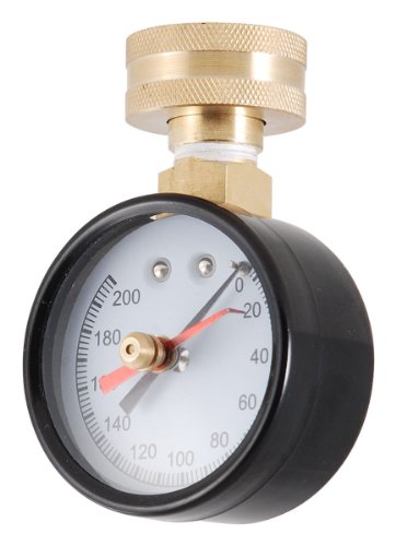
Looking at a pic that gage might be replaceable. A back mount gage like this might work.
www.amazon.com/dp/B016MM67TM/ref=cm_sw_r_cp_api_Gs7ZxbA4M1GJ3
I would do some of these:
https://smile.amazon.com/gp/product/B00C97J5EE
And cobble something together with a raspberry pi or arduino. I don't think I would care to have it just passively telling me the temp, I'd want a logic alert like "Temp in tank X below 60C" or something. Some of the probes out there aren't food grade so buyer beware. I'd design more around what I have... Are there threaded bungs at the top/bottom of the tanks? Can you have some welded in and passivated (assuming stainless)? Epoxy if plastic? etc...
You don't need to buy those pre-made ones. You can just make one yourself with cheapo non-watercooling components. Low-pressure air gauge, a schrader valve, a t-block with one male and two female ends, and a thread adapter. About $20 worth of stuff, assuming you already have something to pump it with.
Throw a ss pressure gauge in the one not being used! May need a few fittings or just throw a ball valve with pressure gauge attached to it because you will need a ball valve on it anyway....
http://www.amazon.com/Ashcroft-Duralife-Stainless-Connection-60/dp/B00FJNLRJG/ref=sr_1_16?ie=UTF8&qid=1422045666&sr=8-16&keywords=stainless+vac+gauge
Cheaper ones are out there for just psi...trying to find one for vacuum and psi at a better price...
To make it clear, this pressure switch is on Neutral for all inline blowers for the three zones. Purpose is - if the HVAC is not blowing air, don't run in-ines.
Hot wires for each zone are managed by Z-wave switches, that only turn on, if the zone needs to meet certain heating or cooling temp.
Problem I have is that in heating mode stage 1, whole system does not have enough pressure in ducts to set off the pressure switch.
From everything I read here, looks my options might be limited to adjustable switch like https://smile.amazon.com/Dwyer-Adjustable-Differential-Pressure-Connection/dp/B00ATGAPD2
What I realized is that if I use one of the RIB relays, in-line blower will start pushing air the moment furnace or compressor turn on but the HVAC blower has not turned on yet. That would lead to unconditioned air to start blowing.
So I got the spout to come off, now for the next part.
Do you think
https://www.amazon.com/dp/B008VO5RHI/ref=twister_B00GGDY6CS?_encoding=UTF8&psc=1
and
https://www.amazon.com/dp/B001PNIL48/ref=twister_B007D995UC?_encoding=UTF8&psc=1
would work also?
There's not a lot to show, but I threw together a couple of quick wiring diagrams:
https://imgur.com/gallery/aKN9joL
Otherwise, here are the links I posted above:
ADC board: WaveShare AD/DA board based on the ADS1256
Diff. Pressure sensor: DIYmore Breakout Board for the MPXV7002 sensor
And here is a PDF of the actual schematic of the WaveShare board as posted from the WaveShare AD/DA page posted prior:
https://www.waveshare.com/w/upload/2/29/High-Precision-AD-DA-board.pdf
Iunlock guide has great information for apply LM the heat sink your wanting is a sunon. http://forum.notebookreview.com/threads/alienware-17r4-15r3-disassembly-repaste-guide-results.797373/
Pressure paper is expensive but I do see it on Amazon they have samples now for like $7 that's the perfect size for 3 or test.https://www.amazon.com/Fujifilm-Prescale-Sample-Pressure-Indicating/dp/B079C5FX6T/ref=mp_s_a_1_3?ie=UTF8&qid=1542136584&sr=8-3&pi=AC_SX236_SY340_FMwebp_QL65&keywords=pressure+paper&dpPl=1&dpID=41Glll94FnL&ref=plSrch Basically it let's you test that even pressure is being made with the die so you can figure out which pads you may want to decrease in height. To be honest with you I didn't use it. it just took me a couple of tear downs adding a little extra LM and then bending the CPU arm on the heatsink to get the core differential down to 4c max.
Good enough. https://www.amazon.com/dp/B07K7HT3XJ/ref=cm_sw_r_cp_apa_i_9rjyDb546KG6G Unfortunately if you're looking for a accurate reading with a fair-weather tool you need to static tubes or what they call pitot tubes
That should probably be fine. I might suggest a somewhat weak test of putting a slight kink in the hose pointing upwards... if the vacuum is struggling against it, it'll suck the hose back to straight.
Sadly, my testing methodology isn't particularly portable. I was given an 11 (?) inch absolute pressure gauge (Heise; this style) from the '60's, which I have up on display on the wall, but for fun is plumbed to a pneumatic quick connect. So I basically just patched it over to the vacuum using some pneumatic hose. A gauge like this could do the job, but TBH I don't think it's worth it unless you have another use for a vacuum gauge.
The connection part was stupid simple though: cut off a few inches of random 1/4" hard plastic tubing, drill 1/4" hole in the F-F coupling connector, jam the tubing in the hole, apply hot glue to prevent leaks. From there, it was just whatever connectors were handy. (I have a set of vacuum hold-down clamps, which helps explain why this array of stuff was readily available)
----
As a significantly less scientific approach, you could connect a host straight to the vacuum, use a blast gate or even just a hand to block the flow varying amounts, and note how the sound changes. Then you can put the same hose setup as you normally use, just without the separator, and see how it sounds. Finally, with the whole setup, again. That should at least give a rough estimate for how much work and flow restriction it's all causing, and establish if it's due to the hoses, or due to the separator.
E: Addendum: that assumes that you have no leaks, and all airflow loss is due to pressure drop. If it doesn't sound like the vacuum is working any harder, but you get noticeably less airflow, then you likely are in the "leaking somewhere" regime. I don't think that's likely though, because you need a pretty enormous leak in order to appreciably affect the vacuuming performance of the Fein.
I use this one paired with this gauge and this connector, and love it.
I hadn't thought about load cells before for this, maybe that will be a simpler approach. I'll try to get a picture of the trays tonight for better context.
Currently each drawer has one long tray that is segmented into the individual trays (usually for keeping sticks of each value). I could potentially build out an inner tray into each of these with a load cell (or a force resistor? would that work? something like: https://www.amazon.com/Sensitive-Resistor-Pressure-Diameter-Resistance-Type/dp/B07MP4RL9Q/ref=pd_cp_147_4?pd_rd_w=rApgs&pf_rd_p=ef4dc990-a9ca-4945-ae0b-f8d549198ed6&pf_rd_r=YJYEX2GZSM394H0DA4W8&pd_rd_r=da7d2b5b-8e6a-4c21-a6a4-186172b7f89a&pd_rd_wg=FPPGa&pd_rd_i=B07MP4RL9Q&psc=1&refRID=YJYEX2GZSM394H0DA4W8) that would sit between the inner and outer trays and determine how many sticks are in that inner tray.
I would be satisfied with just counting "sticks in tray" initially and just specifying individual trays as a particular point value rather than trying to differentiate between sticks.
I made a fixture that screwed the cap lid down. It makes zero difference in the leaks.
I've purchased a nice vacuum gauge, https://www.amazon.com/gp/product/B002JP5PAE which allowed me to eliminate the arduino with BMP183 inside the chamber. I still see the same level of leak, so I feel comfortable that outgassing by the arduino or its battery isn't the cause of the slow increase in pressure.
I noticed that the hose fittings (1/4" flare) are prone to leaking. At this point, it seems like my (pipe-thread and flare) fittings connected to the vacuum chamber are the remaining source of leaks- either they aren't tightened enough, or they have leftover oxygen in the threads.
I haven't completely eliminated outgassing of acrylic as the othe rremaining cause of pressure increase. I guess the only thing I can do is continuously pump the chamber for a couple days without exposing it to atmosphere.