Best semiconductor products according to redditors
We found 357 Reddit comments discussing the best semiconductor products. We ranked the 186 resulting products by number of redditors who mentioned them. Here are the top 20.
We found 357 Reddit comments discussing the best semiconductor products. We ranked the 186 resulting products by number of redditors who mentioned them. Here are the top 20.


These are parts I use consistently in my labs
Capacitor kit
Resistor kit
Jumper wires
Bread board(s)
Larger breadboard. Recommended for larger projects but I haven’t used it too much. Best for large IC circuits
Multimeter. This has all the right features
Other things that can be useful:
•Wire strippers
•Pliers
•Electrical Tape
•Tackle Box or tool bag (to carry everything)
•Flat jumper wires
As you get into classes you’ll need specific parts (transistors, logic gates etc) but this should get you started. I use the things I linked in every lab weekly.
Feel free to message me with any questions.
Honestly getting this was one of the best decisions I ever made:
https://www.amazon.com/AUSTOR-Lengths-Assorted-Preformed-Breadboard/dp/B07CJYSL2T
Breadboard
Also a Breadboard
"A breadboard (or protoboard)"
The terms aren't as clear as you are claiming. Solderless breadboards are also called "protoboards". And solderable PCB boards with pre-drilled holes are also called "breadboards". If you want everyone to understand you, you need to be more explicit than just "breadboard" or "protoboard".
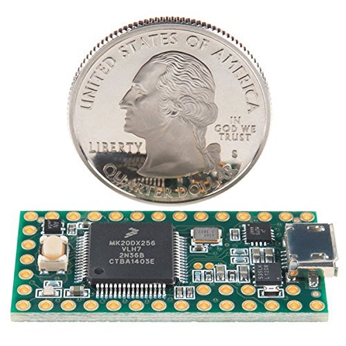
Replace the Arduino with a Teensy3.2; it runs Arduino code and is very small in comparison (with more RAM than the Arduino Uno). Solder the connections to the Teensy. Power the Teensy directly from the battery bank and use a micro USB breakout to convert the battery bank's output to wires that can be soldered into the Teensy. The LEDs should receive power in parallel, not in series. I've found the capacitor unnecessary in every wearable LED project I've done. If you only have single-core wire, helix the three strands together to make a neater cable. I usually build a holster from a coat hanger to hold the battery pack on the hat. It can also go in your pocket.
You can go pretty cheap but the absolute bottom of the barrel Aliexpress ones might have some contact issues. For peripherals it might be good to get this which gives you USB or barrel jack switching, switchable 3.3V/5V, and powers your rails. You also would want a set of prebent jumpers or jumper wire depending on whether you want board cleanliness or ease of routing, respectively.
Not OP, but do you mean the perfboard or teensy?
I'm not sure what level you're at and I'm beginner myself so I'll just go over the stuff I've been doing. Maybe this stuff is super obvious.
> an incomprehensible jumble of jumper wires
If you're not using them already, the pre-cut and pre-bent wires are awesome for keeping things tidy (eg these).
> tightly packed components
Have multiple breadboards - they're like $3-5 at Tayda. The ones that clip together are handy. Having extra real estate to spread things out is invaluable. Although having long jumper wires can introduce more oscillations and noise once you've got things working you can always make things a bit more compact.
Use the buses - the outer two rows that run the length of the board for your power and ground. Use the columns of 5 for your signal path. This way you can just run jumpers up and down for your power/ground. Or if, for example, you have a resistor going to ground you can just connect it directly to the ground bus.
If you use a certain bit of circuitry in a lot of your builds consider making it on veroboard and having it off-board. I've built standard power filtering and reverse polarity protection on vero. You could do the same with something like a voltage doubler or inverter if you're always reusing them. Although it's only a few components it's a bit less on your breadboard and saves you redoing the same thing every time you BB up a circuit.
Try and lay out things as close as they look on the schematic as possible. Ground at the bottom, voltage from the top, signal running left to right. And if you can, down to the individual components. This can be hard sometimes, especially when dealing with transistors/3+ pin devices.
If you've got an old enclosure or something lying around where you can setup your off-board stuff to keep them all tidy makes things easier too. This guide from the Beavis Audio website is a good example. There's a few layout tips in that PDF also. There's also some sample layouts that might be worth a look over for some examples on how to layout certain circuit elements.
Not necessarily related to layout but a few other things I've found:
Test constantly - audio probe and DMM/voltmeter. Grab one of those little pocket battery amps (eg this one for $20) to have on your bench if testing with your real amp is a PITA.
I keep a printed copy of the resistor colour codes on the wall in front of my bench, makes it easy to glance up and check because yeah no way I'm memorising those any time soon.
Draw the pinouts for any ICs/transistors/things with more than two pins on your schematic for quick reference.
Have a decent understanding of the circuit first and how the stages work. I like to redraw stuff in KiCad/Eagle - forces me to learn what connects where. It's a lot easier when you can look at your board and go 'oh I'm missing a resistor that should be connected to the drain' (or whatever) without having to reference your schematic for everything.
I've also found I've been more successful when I'm putting things together to say in my head "signal goes through 68k resistor to gate", "1M resistor connects from gate to ground", "220p cap from gate to ground" etc etc, rather than just going "this thing connects to that". Helps you understand the circuit better and will make you then ask yourself things like "which pin on this component is the gate?".
Like I said, I'm still learning, so if I've said anything blatantly wrong feel free to call me out, always up for getting better.
Get one of these guys, you will most likely need one for any of your lab classes anyway. Look up some simple circuit schematics, and learn to build, it can be much fun. I like this project, and your local radioshack or other electronics place will have everything you need to get started. That chip is an LMC555, a simple 8 pin timer. Once you get in the lab you will presumably have high end multimeters, power supplies, and function generators, but it is good to have a feel for building circuits before you get there, it will put you ahead of your classmates and make your labs a breeze.
You won't be able to do much without either a breadboard or a soldering iron+solder, and in the long run, breadboarding will pay for itself (being that you are a beginner).
Good luck!
Hey there everyone! Sorry for the late followup. I've been unpacking from graduation and the like... Also, as a neat update to my earlier post, I was just contacted by the College Football Hall of Fame to display my cap in the Hall for a few weeks. Neat!
Unfortunately, I didn't take pictures during the build process, but here's my general construction setup.
Supplies needed:
(https://www.amazon.com/gp/product/B00SSY1AJU/ref=oh_aui_detailpage_o00_s01?ie=UTF8&psc=1)
(https://www.adafruit.com/product/1902)
Steps:
General Information
Picture of the Grad Cap During Graduation
Link to Source Video
Arduino Source Code
If you don't want to use a PS/2 to USB adapter, you have a couple of options. One somewhat difficult and one very easy. For both, you'll need to open up the keyboard with a tool like this.
The more difficult way is to use Soarer's Converter software running on a Teensy 2.0. This involves soldering the Teensy to the appropriate pins on the Model M's original controller and flashing the Soarer's Converter software to the Teensy.
I did this with an IBM Model F (AT) and it works great: https://imgur.com/a/ge80k
The easiest option is to purchase a replacement controller from Phosphor Glow. For this, you'll open up the keyboard, remove the original controller and put the new one in. No soldering involved unless you opt for the kit instead of the fully assembled and ready to go board.
I did this on one of my Model M keyboards: https://imgur.com/a/NY78q
This is a Sky Quality Meter used for measuring the light pollution and skyglow at your location. It outputs values in uW/cm^2 for the infrared
and visible specturm and your limiting magnitude in Mag/arcsec^2.
It should be mentioned that these are all Amazon Prime links with two day shipping. If you can wait longer then, you can certainly get these components for far cheaper.
Rocker switch
http://smile.amazon.com/10Pcs-Round-Button-Rocker-Switch/dp/B00AKVBEN6
10 PCS @ $2.47 = $.25
Pushbutton
http://smile.amazon.com/Momentary-Tactile-Push-Button-Switch/dp/B00974ZGPE
10 PCS @ $5.59 = $.56
TSL2591 (High range light meter)
http://smile.amazon.com/Adafruit-TSL2591-Dynamic-Digital-ADA1980/dp/B00XW2OFWW
$11.44
MSP420 Stim32 I2C 128x64 OLED display
http://smile.amazon.com/SMAKN%C2%AE-Serial-128x64-Display-Arduino/dp/B010V0I8DY
$10.80
Arduino Pro Mini 16Mhz
http://smile.amazon.com/Enhancement-ATMEGA328P-Compatible-Arduino-TE362/dp/B015MGHLNA
5 PCS @ $15.99 = $3.20
5V Voltage Regulator
http://smile.amazon.com/Addicore-Positive-Regulator-L7805CV-Antistatic/dp/B00H7KTRO6
5 PCS @ $5.95 = $1.19
Grand total $27.44
You will also need an enclosure and a battery box or some other way of connecting power to the voltage regulator. I 3D-printed my enclosure but, I'm sure you can get
them cheap. As for a battery box, I use this:
http://smile.amazon.com/WAYLLSHINE-Battery-Spring-Plastic-Holder/dp/B019XT18IQ
6 PCS @ $6.98 = $1.16
I have no idea how to price the electrical tape you're going to need in order to cover the miniature star that is the power LED on the Pro Mini.
I suppose you could just desolder it. I'm not that brave. I used a 1/2 piece of black tape and blanketed the LED. Hopefully, not that much light will leak.
Edit edit: This Monoprice DAC/amp is very similar to the V30's audio. Same DAC, same output voltage:
https://smile.amazon.com/Monolith-Hi-Res-DAC-Headphone-Amp/dp/B07BP2WYKZ/
If you do more custom circuit board jobs in the future you may want to get a kit similar to this one. They are meant for breadboard applications but I found they are perfect for custom circuits made on those DIY boards.
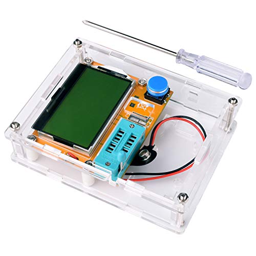
You'd need to disconnect the antenna, yes... but I'd take a guess that the meter you posted won't read capacitance that low anyways. I've had very good luck with this meter when measuring small capacitances, including variables: https://www.amazon.com/Multifunction-transistor-Capacitor-Inductance-screwdriver/dp/B071Y5CHPK it seems to measure down to about 25pf.
The other thing is you might be measuring at the wrong points on the cap. Pay close attention to the mechanism and how it's connected. Put the meter on continuity, and put the leads to the points where you were testing. If you have DC continuity, you're using the wrong points.
I'm an ECE that got into Raspberry Pi about a month ago. I work in microelectronics (chip design), and wanted to use it to get back into larger scale electronics hacking and to do some more hardware oriented programming and projects.
As such, I had to basically reform my electronics gadget supply at the same time since I ditched my college collection a while back when moving to a new house.
Here's some of the key things I bought to go with my Pi that I felt I needed. I'm assuming you're like me and want to work on electronics hardware (lights, switches, etc).
Beyond those basic starter components, the rest is up to your imagination and what you want to do next. In my case, I plan to drive higher current components, so I'll be using optocouples and relays eventually. And I plan to make my own PCBs to snap onto the Raspberry, so I have PCBs, headers, and soldering stuff.
If you're new to the Raspberry, there's online resources out there. I also got this book off Amazon as a starter as well, which I've been coupling with online resources.
On the Arduino side, that's my next purchase since I may find it easier to have the software and server side of one of my projects on a Pi, and the hardware interface on an Arduino. I'm just going to get an R3 board to start since I have the rest of the stuff they usually include in a starter pack listed above.
This blog did a nice writeup comparing some Arduino R3 starter kits:
https://www.pretzellogix.net/2014/10/09/three-arduino-starter-kits-compared-and-reviewed/
To start off you can buy a Teensy 2.0 and follow Hasu's guide. If you need help in the future a PM is welcome.
Thanks. the case and blue keycap are both 3d printed. total cost not including the case and cap is $60 or less. The backlight is not RBG, but I think I've seen some that are.
Big Switch
Teensy 2.0
10mm LED
Switches: any two MX switches will work. NovelKeys has a big selection.
PCB Breadboard? (https://www.amazon.com/Solderable-BreadBoard-matches-tie-point-breadboards/dp/B0040Z6OK6). Thats how those LED graphs are meant to be used. I think that, in addition with resistor packs, would help keep the wiring fairly tidy. Check out this tutorial: https://create.arduino.cc/projecthub/ejshea/led-bar-graph-and-switch-array-8467e0
Really?
https://www.amazon.com/60kHz-atomic-clock-radio-module/dp/B01KH3VEGS
Amazon says this one is in stock. I know there are older boards that aren't made anymore... but in anycase, I'm wondering if I even need the board (and instead can pass a lot of the processing to the ATMega)
I actually didn't tally up the cost as that wasn't really of a concern to me, but I'll try my best to provide links to the things I bought for this. Feel free to add it up for me!
I also bought various tools, like crimpers, Dremel kit, drill, etc, but I don't consider those to be project-specific as I'll have them for the foreseeable future. Let me know if there's anything you see that you think I missed!
You can also buy protoboards that have the holes joined just like a breadboard! They can be really handy for some circuits.
http://www.amazon.ca/gp/aw/d/B0040Z6OK6
Hey guys! While I wait for the rest of my planck parts to arrive I figured I'd build a little 3x3 macro board using my keyswitch tester. I have a teensy 2.0 I got from here. I've soldered the three rows of diodes/grounds together, but I have no clue as to what to do next, is there a guide I could follow or something? The closest thing I've found online is this but it doesn't go into very much detail about the wiring and i have no idea how it carries over to a board this small.
You could also use an LM7805.
https://www.amazon.com/Addicore-Positive-Regulator-L7805CV-Antistatic/dp/B00H7KTRO6/ref=sr_1_cc_1?s=aps&ie=UTF8&qid=1468861711&sr=1-1-catcorr&keywords=lm7805
It really depends on what you're looking to do. I realize at this point you probably don't even know what that is, but a general idea would help.
But for starters, you could get general things like:
The rest is kinda up to what you want to do, but some other suggestions would be:
These kinds of things you'd only need one to test/play with, then if you find a specific application/project, you can order more.
You are looking for something along these lines:
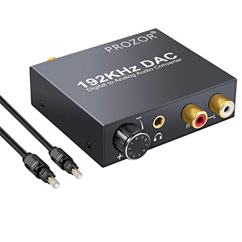
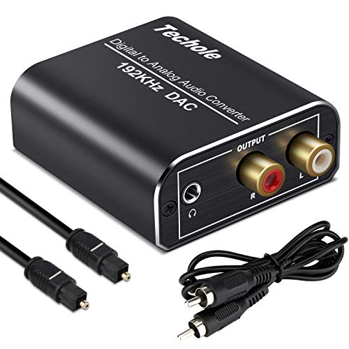
https://amazon.com/Converter-192kHz-Techole-Aluminum-Converter-Headphone/dp/B07MPF4F68/ref=sr_1_4?crid=27BU29OQEP1Y&keywords=toslink+to+rca+converter&qid=1563574281&s=electronics&sprefix=tosl%2Celectronics%2C160&sr=1-4
​
https://amazon.com/ROOFULL-Digital-Converter-Toslink-Optical/dp/B07142SV1D/ref=sr_1_3?crid=27BU29OQEP1Y&keywords=toslink+to+rca+converter&qid=1563574281&s=electronics&sprefix=tosl%2Celectronics%2C160&sr=1-3
​
Or, if you are insane & wealthy:
https://www.berkeleyaudiodesign.com/alpha-dac-reference-series-3
​
p.s. I believe you will need something like this if you don't have it already:
​
https://amazon.com/JSAUX-Shielded-Gold-Plated-Compatible-Smartphones/dp/B07D8M5DML/ref=sr_1_2_sspa?keywords=RCA+male+too+3.5&qid=1563574516&s=electronics&sr=1-2-spons&psc=1
​
https://amazon.com/AmazonBasics-3-5mm-2-Male-Adapter-Cable/dp/B01D5H8JW0/ref=sr_1_1_sspa?keywords=RCA+male+too+3.5&qid=1563574516&s=electronics&sr=1-1-spons&psc=1
You can just buy one of those cheap LCR/component tester jobbies. They're not as good as a real inductance meter but for basic identification they're fine, great for lots of other quick measurements too.
https://www.amazon.com/Multifunction-transistor-Capacitor-Inductance-screwdriver/dp/B071Y5CHPK
Buy some of these.
These are handy too for connecting to modules with header pins.
Don't get too hung up on making everything nice and neat, if you try to get everything tight to the board and the leads all routed straight it just makes it harder to change things.
What you're looking for is a headphone amplifier or a DAC, though I'm not seeing very many headphone amps with TOSLink (optical) built-in. You could use a converter to go from TOSLink to RCA and then use a headphone amp to go from RCA to your headphones. I found this guy on Amazon, but I don't know anything about it and cannot in any way vouch for its quality: https://www.amazon.com/Digital-Optical-Converter-Headphone-Amplifier/dp/B003XCHCLC
Alternatively, if you hook up a home theater system most receivers have a 1/4" jack on them (but that's a lot of expense if you're just trying to get a headphone connection).
EDIT: Ah! After a bit of searching, I think I found exactly what you need: https://www.amazon.com/PROZOR-Digital-Converter-Supports-control/dp/B06XDLCHY7/ref=sr_1_2_sspa?ie=UTF8&qid=1538502346&sr=8-2-spons&keywords=toslink+to+RCA&psc=1
At $22 it's not going to be all that great, but it will get you the connection you're looking for. This will probably sound about as good as the output from your iPod, but it won't compare to a proper headphone amp. If you want a high quality setup, you'll want a high quality DAC paired with a headphone amp.
What headphones are you using?
Monoprice monolith DAC/amp $66 down from $94
https://www.amazon.com/Monolith-Hi-Res-DAC-Headphone-Amp/dp/B07BP2WYKZ/ref=mp_s_a_1_35?ie=UTF8&qid=1542920645&sr=8-35&pi=AC_SX236_SY340_FMwebp_QL65&keywords=dac&dpPl=1&dpID=21VW8V4R%2BmL&ref=plSrch
Here's a diagram - https://imgur.com/a/oS7iO7I
And here are the parts (doorbell not included):
I will note that the rectifier and capacitor that I have listed are likely grossly oversized, I just used what I had on hand since it was a one off project, and I didn't feel like figuring out the proper specifications for them.
I have the Sonoff flashed with Tasmota. You can set the doorbell button up as a button on GPIO 14 through the configuration menu, then set the PulseTime option to 2 (0.2 seconds) in the console, so that the bell doesn't get stuck on if someone holds the doorbell button down.
Another option would be pretty much the same thing I mentioned except for having a volume control. https://www.amazon.com/PROZOR-Digital-Converter-Supports-control/dp/B06XDLCHY7
Awesome! Thank you! I'll have to try to find something similar. That seller has zero feedback, and shipping takes way too long from Hong Kong... : \
Would I be able to find something like that, or something like this locally at a radio shack or something?
Edit
I know the amazon link I put here is 5v, I'm also asking if they make these with 1.25-1.5V Outputs too?
> Yamaha YAS-101
sorry, I didn't register that it was in your title. can you post a picture of your turntable's rear panel? I'm having trouble finding information on it on google. your soundbar doesn't have analog inputs, so you're gonna need an analog to digital converter, unless your turntable has digital outputs, which it sounds like it doesn't
if your turntable has a phono stage, you just need to convert RCA to TOSLINK, something like this analog to digital converter would work
if your turntable doesn't have a phono stage, you'll need one of those as well. so you'd need this phono stage as well as the aforementioned Analog to Digital converted
For the 24vac, you want a rectifier (which can be a simple diode and a small capacitor - google "half-wave rectifier" for designs) and a "buck converter"
For the 110vac, most USB chargers will work just fine for 5v output, and you can use just about any DC wall wart you might have lying around with the aforementioned buck converter.
You could also use linear regulators after the rectifier, but they are much less efficient than a buck converter.
Just need something like this:
https://www.amazon.com/Converter-192kHz-Techole-Aluminum-Converter-Headphone/dp/B07MPF4F68/ref=mp_s_a_1_5?keywords=optical+dac+to+mini&qid=1573778798&sr=8-5
Take optical out of TV into that, then headphone jack to Bose aux input.
IIRC the Dolby Headphone effects aren't applied to the MP3 port. Just something to note. You're only going to get basic stereo sound.
To get surround, you'd either want the old Mixamp, which had analog stereo game inputs, or you can use something like this which will let you hook it up to the optical input.
I've been looking at
this: MCP3008
and
this: Using A Joystick On The Raspberry Pi Using An MCP3008
Reckon that could work?
This might be overkill for what you're trying to do, but...
Monoprice has a 6 zone amplifier. When you say "bluetooth and Alexa compatible," do you mean you want to connect to the speakers with an Echo via Bluetooth? Because if you hardwire the Echo to the amp, this negates the need for a bluetooth receiver, and in fact, the Echo can serve as a bluetooth receiver.
As for your TV sound bar question, the linked amp has pre-amp outs, which you could convert to optical using something like this box.
Does this make sense?
Note: I haven't personally used the products linked, but they are generally well reviewed.
Would this work?
Digital to Analog Audio Converter-192kHz Techole Aluminum Optical to RCA with Optical &Coaxial Cable. Digital SPDIF TOSLINK to Stereo L/R and 3.5mm Jack DAC Converter for PS4 Xbox HDTV DVD Headphone https://www.amazon.com/dp/B07MPF4F68/ref=cm_sw_r_other_apa_i_MoO3DbFK1BRJ2
I use something like this to go from the optical audio output on the PS4 to my older amp via an RCA cable. So PS4>Optical Audio cable>Optical to RCA conversion>RCA cable>Amp
I don't really wanna post the code for ethical reasons (I started with some basic Adafruit code for bluetooth and turned it into a full OS). But here's a feature list:
I used u8g2's u8x8 mode for the screen drawing, as it requires no ram.
​
Here are my parts:
Voltage regulator (takes 8.4v down to 5v)
22pF capacitors
16MHz Oscillator (required for standalone board)
DIYMall blue OLED
Knockoff Arduino Uno
Adafruit UART-Capable bluetooth module (makes sending data easier)
Spare ATMega 328 processors
Li-Ion" 9V" (8.4v) batteries (rechargeable)
Switches
9V battery clip
Soldering Kit
Elegoo prototyping PCBs
Jumper wires (makes life easier & tidier)
Elegoo Starter Kit (Comes with LEDs, resistors, and buttons)
If you search PS4 amp on Amazon you get several results across multiple price points. This for example looks solid but has some reviews you may want to inspect before purchase.
The one I wrote in my original post is one that I own and know works wonders. Unfortunately I haven’t used any of these amps to report and recommend, but more than happy to look around.
You'll need an SPDIF DAC like this one Then you can hook up your wireless headphones to the DAC.
Also, continuous vote tallies are suuuper duper close to being ready to go, and I got the ADC I need to get moisture monitoring set up, sometime...
I picked up an awesome cheap tool I forgot to mention and it was only $15:
https://www.amazon.com/gp/product/B071Y5CHPK/ref=ppx_yo_dt_b_asin_title_o00__o00_s00?ie=UTF8&psc=1
You have to assemble it and it doesn't come with instructions, but it's so good. I use it to test parts before soldering them in, that way I know I have properly working parts before putting them on the board so if I have any problems later, I know it's not the parts. It measures resistors, diodes, caps, transistors, etc. It does the same thing as the $60 atlas DCA and more. The atlas DCA only measure semiconductors, this cheap thing measures passive parts too like resistors/caps, etc. The numbers are slightly different than what my atlas measures, like right now I'm measuring a silicon transistor that is reading 290 hfe on my atlas but 250 on this cheap thing, but it's at least in the right ballpark. The atlas goes into way more detail like leakage and stuff, but the cheap thing at least gives you the hfe and the pinout so you don't accidentally connect the wrong lead to the wrong input. I got a cheap DMM from amazon too that will give you an accurate enough reading for like $15. So for $30, you can have two great measuring tools.
Longer antenna cables are always a better idea than longer USB. To do it right, use an amplifier like this on a short cable right after the antenna, but before a long cable run.
To be clear, like this: Antenna -> short cable to amplifier -> amplifier -> long cable to SDR.
USB cables can be chained together to make really long ones, but you get into timing errors and induced noise if you go longer than 16.5 feet. And then, you're really not sure if what you're hearing is real, or an artifact (induced).
It's this one. I run antenna -> Band Pass Filter -> Amp -> SDR
You can buy them on an electronics store or online. Some people find these to be overpriced though, since all in all it's just a bunch of bent wires. I feel like they save me some time when breadboarding so I bought a couple of boxes a while ago.
Jeg har et par af dem fra en kit.
https://www.amazon.co.uk/Adafruit-MCP3008-856-Converter-Interface/dp/B00NAY3RB2/ref=mp_s_a_1_1?imprToken=8T6MevTUTkATMIt6M60Umw&keywords=MCP3008&linkCode=g13&qid=1563247307&s=gateway&sr=8-1
I suggest getting a 9V or 6V PSU and then run that through a regulator. I use L7805CV when I need a 5V regulator. I literally just used one today to power a arduino pro mini (a 5V micro controller). I suggest using decoupling capacitors with that regulator. 10μF should do the trick. Perhaps if you gave some specifics on what you're building we could be of more help. Usually the micro controllers can power components on their own. They probably wont be able to handle 3A on the 5V pins, but you can use a relay.
I simply used the HiLetGo model which is .100 KHz to 2 Ghz. I enclosed it, mounted 2 connectors for the case, and a knob to vary the voltage from 12v to 5v providing adjustable gain depending on the need. I didn’t design the preamp or anything, just made it look a little more professional. Here’s the link for the amplifier. The case was taken from my old cell phone site I dismantled but I’m sure there are other aluminum cases out there.
Not sure what you bought, but this product listing is for the BB830 and it's a bit more than $3:
https://www.amazon.ca/dp/B0040Z4QN8/ref=sr_1_1?m=A2RKGEIGG4B1JT
What about this?
Also pick up something like https://www.amazon.com/HiLetgo-0-1-2000MHz-Wide-Amplifier-Noise/dp/B01N2NJSGV or an LNA4HF / LNA4ALL if you want much better performance. :-)
Cool, I have been messing with some stuff I have at home already, I am going to go with a Tennsy setup for this. The Teensy 3.2 is small and plenty powerful enough.
https://www.amazon.com/PJRC-6485230-Teensy-3-2/dp/B015M3K5NG/ref=sr_1_1?ie=UTF8&qid=1510164964&sr=8-1&keywords=teensy+3.2
it has an add on board that handles everything else called a "prop board" for doing projects exactly like this. 10DOF motion, 2W amp, controls LEDs also.
https://www.amazon.com/gp/product/B06ZYN7LLC/ref=oh_aui_detailpage_o02_s00?ie=UTF8&psc=1
price is still cheaper than a sound board, and way more configurable.
It's called the Teensy 2.0. You can get them from ebay, amazon, directly from pjrc, but I got mine from Mouser. It is fully programable with the tmk or qmk firmwares.
What I had purchased was- https://www.amazon.com/dp/B07MPF4F68/ref=cm_sw_r_cp_apa_i_rqJqDbYT542E8
are you recommending a 1/4 stereo to RCA connector and connecting that into the headphone jack?
Wow thank you so much, this was very helpful. :)
​
If i am understanding you correctly, this is the new diagram (https://imgur.com/a/Y6XohGa).
​
One question I had was can I use the existing red and black lines to power both the original unit and the buck converter/bridge rectifier/wifi relay? Would i just cut off some of the plastic coatings of the black and red wires somewhere in the middle and wrap the other wires around the two?
My thinking is that this would effectively make two "ends" for the wires that i can use to power the existing circuit board and the buck converter/bridge rectifier/wifi relay.
These work... Depending on the accuracy required for your measurements.
Wow, yeah thats super small. That looks like something that has a specific purpose. Check these out.
https://www.amazon.com/Double-Sided-Board-Prototype-Paxcoo/dp/B01N3161JP/ref=sr_1_1_sspa?ie=UTF8&qid=1522698761&sr=8-1-spons&keywords=perfboard&psc=1
EDIT: Found the problem. You searched for "Perf Board". Try "Perfboard". Here is the same thing on the DE amazon.
https://www.amazon.de/Aihasd-Lochrasterplatte-Lochrasterplatine-Leiterplatte-Universal/dp/B00VL1KHJQ/ref=sr_1_4?s=ce-de&ie=UTF8&qid=1522698858&sr=1-4&keywords=PerfBoard
amazon starter $20
proto practice boards
practice resistors
Yeah, you just need one of these guys
Teensy 2.0
Teensy 2.0 pinout
TMK flashing
Thanks everyone for your insight, this is the LNA I picked up off of Amazon:
https://www.amazon.com/HiLetgo-0-1-2000MHz-Wide-Amplifier-Noise/dp/B01N2NJSGV/ref=sr_1_1?ie=UTF8&qid=1494182132&sr=8-1&keywords=low+noise+amplifier
So far I have to say I'm not seeing much improvement with terrestrial signals from it. I was actually comparing local FM stations with it vs just a basic antenna and it actually seems to be 10 DB less with the LNA powered by 4 AA batteries.
I should be seeing stronger FM signals with the LNA plugged in correct?
Those are the most common type. You can get those off ebay or amazon(i got these recently). Probably cheaper off ebay, but you may wait about a month to get them.
ASUS Gaming z170 something or other mobo (I can get the model later if needed)
Vizio 40" from 2015 > TOSLINK and RCA audio out.
Schiit Modi 2 and Magni 2 Uber
Old Sansui A-5 Stereo amp.
I am using basic cables all around, HDMI, Optical, and RCAs. Once again I have no noise issue when running direct from my PC TOSLINK to the Modi, but if I run through the TV there is noticeable hiss.
I also have a cheap DAC/Amp like this:
https://www.amazon.com/PROZOR-Digital-Converter-Supports-control/dp/B06XDLCHY7/ref=mp_s_a_1_8?ie=UTF8&qid=1540561437&sr=8-8&pi=AC_SX236_SY340_FMwebp_QL65&keywords=dac+amp
It is probably the best option right now but it clutters up my desk with the cable layout. It will work if I have no other option though.
I just wish the Sansui and the Modi shared a connection type. If I could just buy a splitter that would send the signal to both, I'd be fine.
The first item looks like a good starting point for having a small collection of components and a breadboard to test your circuits. Unfortunately if you are looking to get some practice with soldering you are missing an important piece: the actual circuit board. I also use a lot of Pin Headers in my projects, but I like to make things modular and adaptable, so the headers might not be 100% necessary for everyone.
I have a screen very similar to that, and I never use it, since most of my projects are headless, and I just SSH into my Pis remotely. But people are different, you may get a lot of use out of it.
I would also say that you don't need the anti-static mat. Not to downplay ESD, because it can certainly harm your electronics, but you would be much better served with a wrist-strap that clipped onto your computer case or something else that is grounded in your work area.
> cheap out and save a 3.3v regulator (those are expensive for some reason)
Order a handful of LD1117 from Aliexpress, you can get them for $.30/ea
They aren't even that horribly priced an Amazon with prime
Here in this sticky comment you will find an overview of the deals posted in this thread for your benefit. If you find that one of the deals has run out please let me know. Off-topic top level comments asking what to buy will be removed, deals that are missing some of the info will not make it to the list. Also I've changed suggested sorting to "New".
Official Manufacturer Sales
CIEM
Headphones
DACs and Amplifiers and other peripherals
Audio Store
15%5% coupon code "LINSOUL2018" Stackable with existing coupons that are clippable by the Amazon store.Online / Retailer
USA
UK
Sweden
Finland
Australia
Canada
can you tell me what you think about this please??https://www.amazon.com/PROZOR-Digital-Converter-Toslink-Adapter/dp/B06XDLCHY7/ref=sr_1_4?ie=UTF8&qid=1543191372&sr=8-4&keywords=dac&th=1
Use DAC for headphones. You’re GF is going to love that crisp sound.
Here’s the one I used. It’s a 192 khz 24bit DAC amplifier with volume control.
https://www.amazon.com/dp/B06XDLCHY7/ref=cm_sw_r_sms_c_api_B.9-BbE4PRTYF
Tested on Pacific Rim 4k *fight scene, ohh boy it’s so good.
I used to use bluetooth headphones with my pstv and the sound was decent but I recently switched to a toslink converter and the sound quality is much much better. I think most tvs have an optical audio out.
The one I got has no volume control which is a little annoying but you can get a headphone volume knob or this model has one built in.
Gives probably the best setup possible for rhythm games on pstv, music also sounds 10x better.
https://www.amazon.com/PROZOR-Digital-Converter-Supports-control/dp/B06XDLCHY7
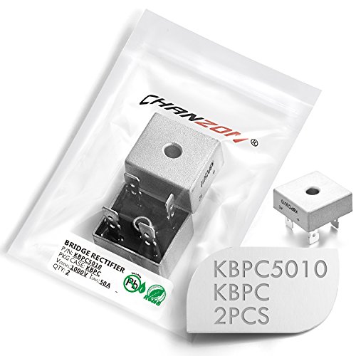
https://www.amazon.com/Pieces-Chanzon-KBPC5010-Rectifier-Electronic/dp/B079KDL8Y5/ref=sr_1_3?keywords=50a+bridge+rectifier&qid=1558967574&s=gateway&sr=8-3
Appropriate rectifiers are cheap and commonly available. You don't NEED a capacitor to make a rectifier work, either, and for this particular application, it wouldn't make any sense to use one.
Getting back to the parent question - a rectifier would work just fine, and only add a few dollars to the cost of the showerhead. I suspect a rectifier WOULD make such a showerhead somewhat safer, too.
Im not good at how to look at how good my dacs is on the motherboard. Here is however the link of it. It does have optical out.
I do have an external [dac](PROZOR Digital to Analog Converter 192kHz DAC Supports Volume control Digital Coaxial SPDIF Toslink to Analog Stereo L/R RCA 3.5mm Jack Audio Adapter https://www.amazon.ca/dp/B06XDLCHY7/ref=cm_sw_r_cp_apap_zzfHEXmPKizcD) which i bought for my ps4. Is that good enough?
I know i said a big ass speaker wont work but I would still like to look into it. Maybe its big enough that it might actually fit in my small ass desk.
You can see the patterns in judgement on the graph in u/pieman445's comment. There's gaps where you simply can't hit the arrow. It could lead to lost steps or late judgements even though you stepped on time. I switched over to a teensy microcontroller and it completely eliminated the problem
Nice switches.
How many do you have to mount?
1-5: and glue them in.
6-20: buy prototyping boards , solder switches and drill holes to mount them.
20+: design a small pcb with mounting holes and have it made in china.
Well a good route could be Fiio D3 for a cheapo DAC with optical in, which I find cleans up a lot of the noise especially when compared to USB DACs. Spend a little more on the amp, which impacts the sound more than the DAC.
PC>optical cable>Fiio D3>RCA>Schiit Magni
Should be under $150 including cables/shipping.
Edit: just saw what you were running. You really don't need much for your headphones. Honestly if you're having problems with a "noisy" source all you'd really need is an optical DAC to clean things up. Your source should provide more than enough power to power your audio technicas.
PROZOR Digital to Analog Converter 192kHz DAC Supports Volume control Digital Coaxial SPDIF Toslink to Analog Stereo L/R RCA 3.5mm Jack Audio Adapter for PS3 XBox HDDVD PS4 Home Cinema Systems AV Amps https://www.amazon.com/dp/B06XDLCHY7/ref=cm_sw_r_cp_api_SFY-yb216G0JC
Cheap and well reviewed.
The current version is on one of those solderable breadboard and it's fairly neat (i.e. four rails for power/ground and then several connected horizontal lines) such as this one: [here] (http://www.amazon.com/Solderable-BreadBoard-matches-tie-point-breadboards/dp/B0040Z6OK6/ref=sr_1_1?ie=UTF8&qid=1377062803&sr=8-1&keywords=solderable+breadboard) .
I was hoping that protoshield was just a solderable breadboard but with Arduino connections on top of it.
Snoothing caps? Is that when you put a capacitor on output, and ground of a voltage regulator? Okay thank you. A while back i bought these voltage regulators, i took a quick look at the spec image they provide, and im still new at reading that stuff but i believe max is 800mA
(12-Pcs) STMicroelectronics 3.3V 950mA, LD1117V33 Voltage Regulator, LD33V https://www.amazon.com/dp/B01N09X4E8/ref=cm_sw_r_cp_apa_i_t.WPDbPV6QP8E
And i bought these heatsinks, and idk if they were a good choice.
50 Pcs 20x15x10mm Black Aluminum Heatsink for TO-220 Transistor https://www.amazon.com/dp/B00UBUOWWG/ref=cm_sw_r_cp_apa_i_EcXPDbP21NCGM
Even sitting across the room, the Klipsch is much louder and fuller. The sub handling mid bass may be the reason?
Another thing that threw me for a loop is that unlike my old TV, the new one doesn't have analog audio out, so I can't simply plug in another set of desktop speakers like I used to. Are you pretty much forced to use a receiver on modern sets, or would something like this be a workable solution?
Considering just returning the whole set and grabbing some wireless surround system that goes on sale next few days.
I don't have a perfect solution for you. Your best bet would most likely be to convert the console optical to analog (rca or 3.5) and use a regular mixer. I also couldn't find a mixer with optical out, so you would then have to convert back to optical, which is kind of lame (unless your transmitter has a 3.5 input).
If you wanted to go this route here is a cheap optical/rca and here is a "cheap" mixer
Here is mine I followed this guide. When I bought mine it was only $14 on Amazon. If you start with the Jellycomb Numpad, you don't have to buy switches or a case... Just the Teensy 2.0 and the diodes.
There may be other options, this one is very easy to get you started.
I've thought about building this very thing for my mom, who can't set a clock to save her life.
I figured it could have the following:
Links:
nope, just something like this
This maybe? http://www.amazon.com/Solderless-Flexible-Breadboard-Jumper-100pcs/dp/B005TZJ0AM/ref=sr_1_3?ie=UTF8&qid=1341350174&sr=8-3&keywords=jumper+wire ?
I've bought a pack of 70 and had lying around too and ran out on a single project! It was so frustrating having to wait for something as simple as wires to be delivered!
It's much tidier and easier than using cut cable
would this work? https://www.amazon.com/PROZOR-Digital-Converter-Supports-control/dp/B06XDLCHY7/ref=redir_mobile_desktop?_encoding=UTF8&dpID=419qZ0dihuL&dpPl=1&keywords=dac%2Bamp&pi=AC_SX236_SY340_QL65&qid=1501564594&ref=plSrch&ref_=mp_s_a_1_7&sr=8-7&th=1
Just to confirm:
ps4 connected to Optical to RCA analog converter
https://www.amazon.com/dp/B06XDLCHY7/ref=cm_sw_r_cp_api_i_2Sx1DbEX2GJC1
Then: RCA to XLR cable run from converter to speakers
https://www.amazon.com/dp/B077L3PG45/ref=cm_sw_r_cp_api_i_IVx1DbM7QG40N
https://www.amazon.com/PROZOR-Digital-Converter-Supports-control/dp/B06XDLCHY7/ref=sr_1_5?ie=UTF8&qid=1505762354&sr=8-5&keywords=dac+amp
Might work if you get this: Digital to Analog Audio Converter-192kHz Techole Aluminum Optical to RCA with Optical &Coaxial Cable. Digital SPDIF TOSLINK to Stereo L/R and 3.5mm Jack DAC Converter for PS4 Xbox HDTV DVD Headphone https://www.amazon.com/dp/B07MPF4F68/ref=cm_sw_r_cp_apa_i_om5QDbD3PC444
You'll need to go digital out from the TV then convert to the RCA red and white in to video 1 on the receiver.
Not noticeable
I use a very simple and cheap one, looks like this
https://www.amazon.com/avedio-links-Digital-Converter-Adapter/dp/B00N8UYGMW/ref=sr_1_8?crid=2VFOBMU4APTO0&keywords=toslink+analog+to+digital&qid=1554578709&s=gateway&sprefix=toslink+analog%2Caps%2C234&sr=8-8
Aww, come on, give OP a break, reading is hard.
Here's a basic one you can do at home:
Here is the mobile version of your link
Similar to what I'm trying....
Just ordered this last night:
https://www.amazon.com/gp/product/B00N8UYGMW/ref=oh_aui_detailpage_o00_s00?ie=UTF8&psc=1
My hope is to go monitor>beam.
Monitor 3.5 port > RCA Y cable > LinkS adapter link > Toslink/Digital optical > HDMI adapter included with the beam.
Not sure if that is exactly what you're looking for or not. But if so I can tell you tomorrow or the day after when it shows up.
Using this ADC and using this sensor hooked up to a raspberry pi and breadboard with pi cobbler type attachment. Still waiting on the ADC to come in from Amazon.
Karlsson Robotics is the only legitimate seller.
edit: Looks like Sports Internet Solutions is also an official distributor.
https://www.amazon.com/gp/product/B00NC43256/ref=ox_sc_act_title_1?ie=UTF8&psc=1&smid=AFBMYHRQ9KU5H
https://forum.pjrc.com/threads/23601-Official-Distributors
Likely to get a fake from any other seller.
Also, it's a dollar less buying it directly from PJRC.com. $16 + $4 postage.
https://pjrc.com/store/teensy.html
Theres a lot of guides out there and most of the hard work has been done for you. You can buy a kit with a pcb, case and switches.
However if you want to build a fully custom keyboard you can try to follow what I tried the other day.
Theres a few things parts youll need for a keyboard.
You'll need to wire your switches into a matrix. Make sure the switches are in the right orientation. Wire them to the pins on your microcontroller. Make sure they match with the rows and columns that you chose on the QMK. Lastly, you need to flash your keyboard. Theres a few guides online for this, but if you choose the teensy you can follow this.
and a teensy 2.0 ... just the base one .... it has a female MINI usb, right? not a micro?
http://www.amazon.com/gp/product/B00NC43256?psc=1&redirect=true&ref_=ox_sc_act_title_3&smid=AFBMYHRQ9KU5H
Diodes and Teensy model I'm considering
I think you'll be happy to know moving from a breadboard to a permanent circuit can be made a lot easier. I've used those individual unconnected ones before and it's pretty miserable trying to make blob shorts all day. A piece of wire helps but i start to feel like I'm making wire origami art.
What you're looking for is called a solderable breadboard there are others that move the power rails back to the outside but this helps save space.
My dad passed down his Martin Logan Vantages and his Krell kav 400xi amplifier to me. Growing up with him I was used to listening to them with a pretty high end source (he had a high end record player and CD player.) He kept the sources, so this is my current setup:
XBox sends sound to TV via HDMI, then through the optical audio out on the TV to a DAC (https://smile.amazon.com/gp/product/B06XDLCHY7/ref=oh_aui_detailpage_o07_s00?ie=UTF8&psc=1), which is connected directly to the amp.
I typically am just streaming Spotify, but I often hear distortion in songs where previously there was none. It just doesn't sound too good. I don't really own CDs; streaming music is what I do. I know I won't get the same high-end sound as a CD or a vinyl, but what would be your recommendation for a source that will stream to the krell amp?
Thanks!
From Amazon:
> When the power supply voltage changes in 5-8 v, it can be used as a variable gain amplifier, gain increases with the increase of the power supply voltage, which suitable for radio frequency receive front-end circuit, using DA control power supply voltage, to control the gain of the amplifier, automatic gain control
> When the power supply voltage in the 8-10 v, the low frequency end gain up to 30 db, at this time the amplifier has a low noise coefficient and good stability.
> When the voltage is 12 v, reach maximum gain, the low frequency end gain of 32.5 dB.
https://www.amazon.com/HiLetgo-0-1-2000MHz-WideBand-Amplifier-Noise/dp/B01N2NJSGV
You can use an optical to rca or 3.5mm converter. That is if your PS4 had optical audio out. I can't remember if the slim model does.
I used to use one to connect up a high quality headphone amp for my sim racing setup.
Digital to Analog Audio Converter-192kHz Techole Aluminum Optical to RCA with Optical &Coaxial Cable. Digital SPDIF TOSLINK to Stereo L/R and 3.5mm Jack DAC Converter for PS4 Xbox HDTV DVD Headphone https://www.amazon.com/dp/B07MPF4F68/ref=cm_sw_r_cp_apa_i_4L7UDbTX1DTDP