(Part 2) Top products from r/PrintedCircuitBoard
We found 22 product mentions on r/PrintedCircuitBoard. We ranked the 47 resulting products by number of redditors who mentioned them. Here are the products ranked 21-40. You can also go back to the previous section.
21. WITMOTION USB-UART 6-in-1 Multifunctional(USB-TTL/RS485/232,TTL-RS232/485,232 to 485) Serial Adapter, with CP2102 Module Compatible with Windows 7,8,Linux,Arduino, for develeopment Projects
Sentiment score: 1
Number of reviews: 1
Six-in-one Multifunctional Serial adater supports usb-ttl, usb-rs232, usb-rs485, ttl-232, ttl-485, 232-485 converting function, freely convert to each otherUSB specification 2.0 is compatible with Windows XP/7/8/10 32bits/ 64bits, Linux, Wince, Mac, Vista etc.Equipped with superior-quality mode swit...
 Show Reddit reviews
23. AOYUE 936 Soldering Station
Sentiment score: 0
Number of reviews: 1
Newly designed Configurable Soldering Iron HolderThis is a 35 watt soldering station1 degree C controlEasy to use
 Show Reddit reviews
24. The Art of Electronics
Sentiment score: 1
Number of reviews: 1
Cambridge University Press
 Show Reddit reviews
26. Printed Circuit Board Design Techniques for EMC Compliance: A Handbook for Designers
Sentiment score: 0
Number of reviews: 1
Used Book in Good Condition
 Show Reddit reviews
27. Make: Analog Synthesizers: Make Electronic Sounds the Synth-DIY Way
Sentiment score: 1
Number of reviews: 1
Maker Media Inc
 Show Reddit reviews
28. Arctic Alumina Thermal Adhesive 5g
Sentiment score: 1
Number of reviews: 1
Arctic Alumina Adhesive uses a layered composite of aluminum oxide and boron nitride.Arctic Alumina Adhesive is a pure electrical insulator, neither electrically conductive nor capacitiA set of Arctic Alumina Thermal Adhesive consists of two tubes containing a total of 5 grams
 Show Reddit reviews
29. Krylon K05130107 ColorMaster Acrylic Crystal Clear, Gloss, Clear, 11 oz.
Sentiment score: 1
Number of reviews: 1
For use on plastic, metal, wood and morePerfect for indoor and outdoor projectsDries in 10 minutes or lessDurable Covermax technology for premium coverage and brilliant color.
 Show Reddit reviews
30. Ruby Chemical 2OZ Liquid Rubyfluid
Sentiment score: 0
Number of reviews: 1
flux liquid rubyfluid. solderingCOUNTRY OF ORIGIN US
 Show Reddit reviews
31. Powerex MH-C800S 8-Cell Smart Charger for AA / AAA NiMH / NiCD,Grey
Sentiment score: 1
Number of reviews: 1
8 independent smart charging circuits capable of charging 1-8 AA/AAA batteries in any combinationA large LCD screen shows the charging status of each batteryYou have a choice of rapid and soft charge modes. Rapid charge enables 8 batteries to be fully charged to their maximum capacities in 1-2 hr. S...
 Show Reddit reviews
32. Arctic Star AR550 Mini Infrared Thermometer
Sentiment score: -1
Number of reviews: 1
Best accuracy in its class: + 2% of readingTake accurate temperature readings with this handheld gunRed laser pointer for precise aimingMeasures in Celsius or Fahrenheit (Range: -32 ° C to +550 ° C / -26 ° F to +1022 ° F)Batteries not included.
 Show Reddit reviews
33. New ATTEN AT 858D+ 858D SMD Hot Rework Digital Station Air Solder Blower Gun
Sentiment score: 0
Number of reviews: 1
 Show Reddit reviews
34. Hitec RCD Inc. Servo Wire: 50' 3-Color, HRC57417
Sentiment score: 1
Number of reviews: 1
<b>Hitec 50', 3 Color Servo Wire</b><br><br>Need to make servo extensions? This Servo Wire is good f
 Show Reddit reviews
35. Breville BOV800XL Smart Oven 1800-Watt Convection Toaster Oven with Element IQ, Silver
Sentiment score: 1
Number of reviews: 1
Element IQ delivers the right power at the right time and when adjusted to taste, remembers1800 Watts with 5 quartz heating elements. Capacity: 6 Slice Toaster, 13 inch Inch Pizza. Voltage 110 120 VoltsBacklit, easy read LCD changes from blue to orange when cooking1 year limited product warrantyExte...
 Show Reddit reviews
36. Portasol 011289250 Pro Piezo 75-Watt Heat Tool Kit with 7 Tips
Sentiment score: 1
Number of reviews: 1
Kit includes 4 soldering tips, hot air and deflector, hot knife a a short distance from tip to gripClick-to-ignite, 60 minute run time, ready to melt solder less than 30 seconds from ignitionAdjustable temperature control, 10 second refill time, refills with butane lighter gasUltrasonically welded g...
 Show Reddit reviews
37. BLACK+DECKER Countertop Convection Toaster Oven, Silver, CTO6335S
Sentiment score: 0
Number of reviews: 1
Included Components: Removable Crumb Tray
 Show Reddit reviews
38. Hakko T18D16P Tip for Fx-888 Station, 1.6mm
Sentiment score: 0
Number of reviews: 1
This product is made from high quality materials, and it is designed for lasting performanceUse Hakko for all of your hobby soldering needs and experience the differenceThis is for use with FX-8801/907/900M/913Shape: ChiselDimensions: 1.6 mm x 14.5 mm
 Show Reddit reviews
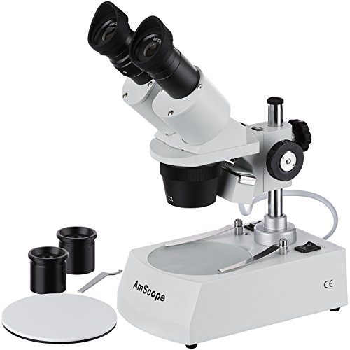
39. AmScope SE305R-PZ Forward Binocular Stereo Microscope, WF10x and WF20x Eyepieces, 10X-60X Magnification, 1X and 3X Objectives, Upper and Lower Halogen Light Source, Pillar Stand, 120V
Sentiment score: -1
Number of reviews: 1
10X-20X-30X-60X stereo magnification settingsHigh quality widefield optical glass lensesForward widefield binocular headSturdy pillar stand with metal frameworkBuilt-in incident (top) and transmitted (bottom) lights
 Show Reddit reviews
40. AmScope SM-4B-FRL Professional Binocular Stereo Zoom Microscope, WH10x Eyepieces, 7X-45X Magnification, 0.7X-4.5X Zoom Objective, 8W Fluorescent Ring Light, Double-Arm Boom Stand, 110V-120V
Sentiment score: 1
Number of reviews: 1
Professional stereo microscope with boom stand has long working distance to enable users to perform work or manipulate large items, including circuit boards and dental appliancesBinocular viewing head with pair of 10x super-widefield eyepieces, adjustable interpupillary distance, fixed 45-degree ver...
 Show Reddit reviews
I did learn all of this stuff from experience. Honestly, I had a little bit of a tough time right out of college because I didn't have much practical circuit design experience. I now feel like I have a very good foundation for that and it came through experience, learning from my peers, and lots of research. I have no affiliation with Henry Ott, but I treat his book like a bible . I refer to it just about every time I do a board design. Why? because it's packed with this type of practical information. Here's his book. I bought mine used as cheap as I could. At my previous job, they just had one in the library. Either way, it was good to have around.
So why should you care about electromagnetic compatibility (EMC)? A couple reasons:
Anyways, it's definitely worth looking at and is a huge asset if you can follow those guidelines. Be prepared to enter the workforce and see rampant disregard for EMC best practices as well as rampant EMC problems in existing products. This is common because, as I said, it's not taught and engineers often don't know what tools to use to fix it. It often leads to expensive solutions where a few extra caps and a better layout would have sufficed.
A couple more books I personally like and use:
Howard Johnson, High Speed Digital Design (it's from 1993, but still works well)
Horowitz and Hill, The Art of Electronics (good for understanding just about anything, good for finding tricks and ideas to help you for problems you haven't solved before but someone probably has)
Last thing since I'm sitting here typing anyways:
When I first got out of college, I really didn't trust myself even when I had done extensive research on a particular part of design. I was surrounded by engineers who also didn't have the experience or knowledge to say whether I was on the right path or not. It's important to use whatever resources you have to gain experience, even if those resources are books alone. It's unlikely that you will be lucky and get a job working with the world's best EE who will teach you everything you need to know. When I moved on from my first job after college, I found out that I was on the right path on many things thanks to my research and hard work. This was in opposition to my thinking before then as my colleagues at my first job were never confident in our own ability to "do EE the right way" - as in, the way that engineers at storied, big companies like Texas Instruments and Google had done. Hope that anecdotal story pushes you to keep going and learning more!
In my experience searching for similar things, the conclusion I reached was that to get anything better than the T962 (which is utter shit, to be clear) you need to spend several thousand dollars.
I took the plunge on building a reflow oven using this toaster and a Controleo 2, plus copious amounts of expensive tape and some ceramic blanket insulation from McMaster-Carr. Do NOT use the felt crap on Amazon that's intended for cars, the temperature ratings are horseshit and are for "radiant" heat, they won't actually stand up to 2,000deg or even 500.
It took about a week of 1-2 hours per day, but the result was well, well worth it. It's performed absolutely flawlessly the last 2 years and reflows beautifully every time. Lead-free BGAs are no problem, it's been stellar. I probably spent something like $500 on it but you can do it for less. The oven was $200, ceramic blanket roll about $40, extra reflective tape ~$100, plus other odds and ends.
One thing I did with that toaster was use thin aluminum sheet metal to make "shields" for the upper heating elements so there is no direct IR on the boards. Combined with a convection oven, this goes a long way towards ensuring even heating and no hot-spots. Much better than scorching a batch of boards you spent the entire day assembling as I've done with the T962.
The oven I got is probably overkill, it works well but due to the size the reflow cycle runs on the long side. Still within the IPC spec, however.
IMHO it's the only way to go unless you're willing to pony up for a proper commercial oven. The only thing that might be better is vapor-phase reflow which you can accomplish for relatively little (the fluid is extremely expensive however), but that method is also more labor intensive.
Keep in mind that with any oven you should profile it - really just do a test run - before putting in a batch of boards. The worst that will happen if you've done it right is that the solder might not reflow everywhere. When that happens I bump the peak temperature up by 5-10deg C and run it again, but it's better to get it the first time while the flux is still active. Profiling is simple, I take 2-3 random bare PCBs I have laying around, put a few blobs of whatever solder paste I'm using on the pads, and put them on opposite ends of the oven. Run a cycle and if it reflows you're pretty much good to go. Takes 5 minutes.
So yeah, not to pimp my oven too hard but for the situation you're in I'd say 100% build your own. Getting better results will require you spending 5-10x as much.
EDIT: Assembly pics for the curious! I threw them all in there, sorry they're out of order. That grey stuff was the "ULTRA OMG HIGH TEMP RACECAR" insulation from Amazon I used on the first attempt. Do not want. Only after I put it all in there I realized it shouldn't be in contact with a 500deg oven. Gets a little melty. I ended up getting this ceramic blanket from McMaster which is the white insulation you see later. I added it to the window after testing without because it cuts own on heat loss dramatically and makes it easier to hit the right profile. It gets everywhere though and is very itchy, similar to fiberglass insulation, so be warned. Once it's assembled then no worries.
You can also see the shields I added to the upper heating elements to eliminate direct IR.
Spend $400 on a proper binocular (or even trinocular if you expect to take lots of pictures) scope with a ring LED to light your work from the top, and a proper base at the bottom.
The SM-3B series (-3T for trinocular) is great. And the more secure double-boom of the SM-4B/-4T series is even better.
I would get the 3.5x-90x combo set which includes the 0.5x and the 2x len attachment. Most of the time, I'm in the 7x-45x range, so if you just get this guy with the ring light, you'll be good to go.
The $400-$600 you spend now will last you for the rest of your life.
Similarly, spend a little more on your first good iron. I bought my Hakko 926 when I was in college. Spent $300 on the setup then. That was about 20 years ago. Still my primary iron.
Sure, you can basically go as simple or as complex as you'd like. The most basic "synth" You could make would probably be a tone generator based on the 555 timer, something like the Atari Punk Console. Music From Outer Space is a good resource for more involved synth projects and the book Make: Analog Synthesizers is a pretty popular resource (you can find pdf versions online). Finally, r/synthDIY has some good resources too.
The waveshare ESP32 board is a good open source reference you can use: https://www.waveshare.com/w/upload/8/80/E-Paper_ESP32_Driver_Board_Schematic.pdf (I'm guessing you already did based on similarities).
If you don't need the extra accuracy, you can recover 2 gpios by dropping the external crystal. I'm not sure it's that well supported (at least in Arduino) and if you need an accurate clock, you can add a cheap I2C RTC which can share the I2C bus with other sensors. Speaking of sensors, most sensors are available in an I2C version which don't use any additional pins.
I usually also leave off the USB-serial converter and just put a 2x3 header breaking out TX/RX/DTR/RTS/3V/GND. I have a cable I made up that goes from my usb-serial converter (this one) to the onboard header.
Keep in mind that some of the pins are input only, looking at the names on the schematic, I think you took that into account, but verify.
You use really high resistor values in the battery measurement circuit, I know there is an upward limit beyond which the ADC won't work reliably. Since it looks like you are trying to turn on/off the resistor divider, you can use lower resistances. Check out these references (one, two). I used something like Nick's answer to this SE question in my own design. If you're doing a rechargable battery, you should really consider a lipo fuel gauge IC instead though. It'll give you a much better indication of battery charge than voltage alone.
It looks like aluminum PCBs have a different dielectric material between the copper layer and the aluminum, which is what gives them the superior thermal characteristics... very interesting:
http://www.amitroncorp.com/printed-circuit-boards/aluminum.html
Also, I was going to ask if the design has room for a heat sink? I've used thermal epoxy quite a lot for a variety of applications, and been very happy with the results in both adhesion and heat transfer capabilities.
https://www.amazon.com/Krylon-Colormaster-Crystal-Clear-Acrylic/dp/B0009X8LZ4
That is what is currently being used. I don't see how this helps all that much to be honest. They have been doing this for years though.
We also handling the boards to much imo. We get them from our supplier then program them, test them, spray them then mount them. Ideally it'd be nice to find a company that could send them 100% complete to us. If you have any recommendations that would also be appreciated.
This was my gateway drug to the 32 ft of workbench space that now contain an oscilloscope, a reflow oven, a stereo microscope, 3 soldering and hot air rework stations, and hundreds of boxes of pinhead sized components along with dozens of sensors for different things.
I'm enjoying my trip down the rabbit hole :D
I linked that video because I used my wife's expensive tweezers to place the components because I was too excited to wait for the proper ESD safe ones later in the video.
Gratz on your boards!
Thanks for the help. I will definitely check it out. The one I ended up ordering was:
http://www.amazon.com/gp/product/007142783X?psc=1&amp;redirect=true&amp;ref_=oh_aui_detailpage_o00_s00
It has some really good reviews so I hope it holds up.
it would need at least detailed sharp, pics of both sides of the board and clear picture or schematics of the wiring.
OTOH, you do get what you pay for. Is $60 too much for being sure that your house doesn't burn down because of a cheaply made junker? Fixing the problems in the cheap one would likely cost more than that.
Finally, a much better solution than these chargers is to buy a normal fast charger for 4-8 AA cells. Some of those chargers will charge a pack in 60 minutes, there were even some that did it in 15 (but those needed special type of NiMh cells).
E.g. something like this:
https://www.vapextech.co.uk/fast-smart-charger-for-1-8-aa-or-aaa-nimh-batteries-lcd-display-vapextech/
That has both fast charging, detection of a faulty battery and trickle charge maintenance, so that the batteries are always topped up and ready to go. That is vastly more capable than the charger you have found and costs about the same.
Or this one - a bit more expensive but the charging time doesn't increase with the number of batteries inserted:
https://www.amazon.com/Powerex-MH-C800S-8-Cell-Smart-Charger/dp/B000LQMKDS
Yes, I get it that replacing batteries is a pain in the backside compared to just plunking the remote on a charger but you get much better life out of the batteries by separately charging each cell.
> I can find a lot of online resources on 2 layers rules and gotchas, 4 layers seems less common, any good pointers?
Montrose - https://www.amazon.co.uk/Printed-Circuit-Design-Techniques-Compliance/dp/0780353765
Full book here: https://d1.amobbs.com/bbs_upload782111/files_16/ourdev_457787.pdf
This article talks about dedicated layers: https://www.emcstandards.co.uk/files/part_5_text_and_graphics_21_may_09.pdf
The Circuit Designer's Companion was a great resource when I was getting started. I've got the second edition and still use it from time to time. I think they're on the third edition now. ISBN 0-7506-6370-7
Sorry, I figured giving you an off-the-shelf equivalent would have been easier for you. The actual cable was made using standard servo wire, the mating housing, and crimp pins.
http://www.amazon.com/Hitec-59411-Servo-Wire-Color/dp/B001BHLTG0
https://www.digikey.com/product-detail/en/61900311621/732-2868-ND/2508637
https://www.digikey.com/product-detail/en/61900113722DEC/732-2871-ND/2508640
I bought a toaster oven and the ControlLeo Kit. But I haven't modded it yet. I just put the boards in and baked with convection... after about 4-5 minutes, they are ready.
Here's the oven I purchased on amazon:
[toaster oven] (https://www.amazon.com/gp/product/B0043E6PLC/ref=oh_aui_detailpage_o06_s01?ie=UTF8&amp;psc=1)
You can mitigate a lot of problems with a drop liquid flux from a needle tip bottle. A better iron will help too.
This article recommends a Hakko 936 for about $80:
This looks similar for $45:
Does anyone own either one of these?
well let's see, not so good iron, not so good solder, wrong flux = no mystery there.
Ditch the USB microscope and get a real scope. I tried the USB and it was terrible. I ordered this scope and have had no regrets.