(Part 2) Top products from r/arduino
We found 102 product mentions on r/arduino. We ranked the 1,463 resulting products by number of redditors who mentioned them. Here are the products ranked 21-40. You can also go back to the previous section.
21. Weller WES51 Analog Soldering Station
Sentiment score: 4
Number of reviews: 5
Receptacle For Easy Iron ReplacementDesigned For Continuous Production SolderingSlim, Comfortable Pencil With Eta Tip Reduces Operator FatigueTip Temperature Offset CapabilityAllows User To Reset Station Temperature To Match In Tip Sizes & StylesStation Includes Power Unit, Soldering Pencil, Stand a...
 Show Reddit reviews
22. SunFounder 2 Channel DC 5V Relay Module with Optocoupler Low Level Trigger Expansion Board for Arduino R3 MEGA 2560 1280 DSP ARM PIC AVR STM32 Raspberry Pi
Sentiment score: 3
Number of reviews: 5
5V 2-Channel Relay interface board, and each one needs 15-20mA Driver CurrentEquiped with high-current relay, AC250V 10A ; DC30V 10AStandard interface that can be controlled directly by microcontroller (for Arduino ,Raspberry Pi, 8051, AVR, PIC, DSP, ARM, ARM, MSP430, TTL logic)Indication LED's for ...
 Show Reddit reviews
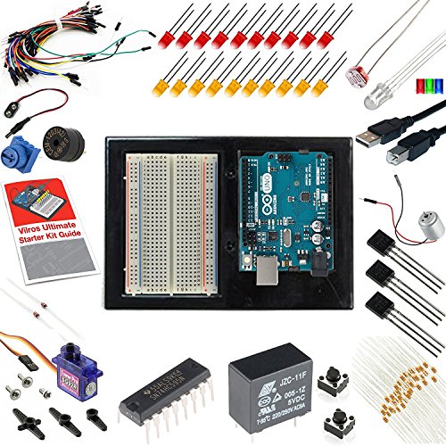
23. Vilros Arduino Uno Ultimate Starter Kit + LCD Module - Includes 72 Page Instruction Book
Sentiment score: 4
Number of reviews: 5
The ulitamate Arduino Uno kit to get you started with hundreds of arduino projectIncludes the Arduino Uno Rev3 BoardBread Board -- Holder -- Jumper Wires -- USB Cable -- LEDs -- DC Motor -- Small Servo -- RelayIncludes 16x2 LCD with soldered Pin header72 page full color Instruction Manual
 Show Reddit reviews
24. EMY 5 X HC-SR501 Adjust Ir Pyroelectric Infrared PIR Motion Sensor Detector Modules
Sentiment score: 2
Number of reviews: 5
PCB Dimensions: Approx. 32 x 24mmOperating voltage: DC5V to 20VLevel output: 3.3V, low 0VDelay time: adjustable (0.3 seconds to 18 seconds)
 Show Reddit reviews
25. SainSmart 8-Channel Relay Module
Sentiment score: 3
Number of reviews: 5
5V 8-Channel Relay interface board, and each one needs 15-20mA Driver CurrentEquipped with high-current relay, AC250V 10A ; DC30V 11AStandard interface that can be controlled directly by microcontroller (Arduino , 8051, AVR, PIC, DSP, ARM, ARM, MSP432, TTL logic)Indication LED's for Relay output sta...
 Show Reddit reviews
26. SainSmart 4-Channel Relay Module
Sentiment score: 2
Number of reviews: 5
5V 4-Channel Relay interface board, and each one needs 15-20mA Driver CurrentEquipped with high-current relay, AC250V 10A ; DC30V 10AStandard interface that can be controlled directly by microcontroller (Arduino , 8051, AVR, PIC, DSP, ARM, ARM, MSP431, TTL logic)Indication LED's for Relay output sta...
 Show Reddit reviews
27. Joe Knows Electronics 1/4W 1% 86 Value 860 Piece Resistor Kit
Sentiment score: 2
Number of reviews: 5
1/4W 1% Tolerance Metal Film Resistors.10 each of 86 standard E12 values from 0 ohm to 10M ohm.High quality extra thick copper lead wires.Each ohm value individually packaged and neatly labeled for easy organization.Sorted by ohm value. Find each ohm value quickly without reading color bands.
 Show Reddit reviews
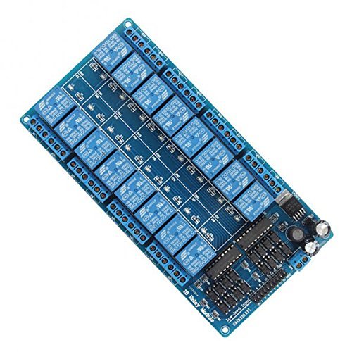
28. SainSmart 16-Channel Relay Module
Sentiment score: 2
Number of reviews: 5
12V 16-Channel Relay interface board, and each one needs 15-20mA Driver CurrentEquipped with high-current relay, AC250V 10A ; DC30V 12AStandard interface that can be controlled directly by microcontroller (Arduino , 8051, AVR, PIC, DSP, ARM, ARM, MSP433, TTL logic)Indication LED's for Relay output s...
 Show Reddit reviews
29. KEDSUM HC-06 Serial Slave Module, Wireless RF Transceiver Module with DuPont Cable
Sentiment score: 3
Number of reviews: 5
Industrial serial port bluetooth, Drop-in replacement for wired serial connections, transparent usage. You can use it simply for a serial port replacement to establish connection between MCU and GPS, PC to your embedded project and etc. Computer and peripheral devicesGPS receiver Industrial control ...
 Show Reddit reviews
30. 0.96 Inch Yellow and Blue I2C IIC Serial 128X64 OLED Display Module for Arduino
Sentiment score: 1
Number of reviews: 5
Supported voltage: 3.3V-5V DCDriver IC: SSD1306Communication: IIC, only two I/O portsViewing angle: greater than 160 degreesSize: 0.96 inches
 Show Reddit reviews
31. Breadboard Jumper Wire 75pcs pack
Sentiment score: 1
Number of reviews: 4
jumper wiresmale to male
 Show Reddit reviews
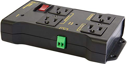
32. Iot Relay - Enclosed High-power Power Relay for Arduino, Raspberry Pi, PIC or Wifi, Relay Shield
Sentiment score: 2
Number of reviews: 4
Safe, Reliable Power ControlOne circuit, 4 outlets, 2x NC, 2x NOWires to your Arduino, Raspberry Pi, PIC, or other microTakes the place of a relay board. Fully assembled and ready to use.Includes surge supression, debounce, safety breaker
 Show Reddit reviews
33. JBtek 4 Channel DC 5V Relay Module for Arduino Raspberry Pi DSP AVR PIC ARM
Sentiment score: 3
Number of reviews: 4
Equiped with high-current relay, AC250V 10A ; DC30V 10A5V 4-Channel Relay interface board, and each one needs 50-60mA Driver CurrentBe able to control various appliances, and other equipments with large currentApplication:Supports all MCU control, The industrial field, PLC control, Smart home cont...
 Show Reddit reviews
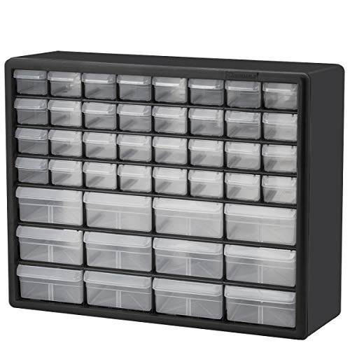
34. Akro-Mils 44 Drawer 10144, Plastic Parts Storage Hardware and Craft Cabinet, (20-Inch W x 6-Inch D x 16-Inch H), Black (1-Pack)
Sentiment score: 2
Number of reviews: 4
CABINET DIMENSIONS- 20-Inch x 6-3/8 Inch x 10-1/4 Inch, DRAWER DIMENSIONS- 6-Inch x 2-1/4 Inch x 1-5/8 Inch (small drawer), 6-Inch x 4-1/2-Inch x 2-3/16-Inch (large drawer)HIGH QUALITY- Rugged, high-impact polystyrene plastic frame and 44 drawersGREAT FOR– Storing and organizing classroom or offic...
 Show Reddit reviews
35. SainSmart 2-Channel Relay Module
Sentiment score: 2
Number of reviews: 4
5V 2-Channel Relay interface board, and each one needs 15-20mA Driver CurrentEquipped with high-current relay, AC250V 10A ; DC30V 10AStandard interface that can be controlled directly by microcontroller (Arduino , 8051, AVR, PIC, DSP, ARM, ARM, MSP430, TTL logic)Indication LED's for Relay output sta...
 Show Reddit reviews
36. Qunqi L298N Motor Drive Controller Board Module Dual H Bridge DC Stepper For Arduino
Sentiment score: 2
Number of reviews: 4
Dual-channel H-bridge driver working mode creates higher working efficiency,L298N as main chip.Can drive one 2-phase stepper motor, one 4-phase stepper motor or two DC motors.To avoid damage the voltage stabilizing chip, please use an external 5V logic supply when using more than 12V driving voltage...
 Show Reddit reviews
37. Programming Arduino: Getting Started with Sketches, Second Edition (Tab)
Sentiment score: 3
Number of reviews: 4
McGraw-Hill Education Tab
 Show Reddit reviews
38. Makerfire 10pcs Arduino NRF24L01+ 2.4GHz Wireless RF Transceiver Module New
Sentiment score: 1
Number of reviews: 4
Brand New, 90 Days WarrantyModel: NRF24L01
 Show Reddit reviews
39. Tamiya 70168 Double Gearbox
Sentiment score: 1
Number of reviews: 4
Made from high quality materials and designed for long lasting performanceUse Tamiya stock and hop-up replacement parts, accessories, and more to get the most out of your modelsThis is for use on RC and model products, consult your user's manual for exact parts listingsPackage dimensions: 6.1" L x 4...
 Show Reddit reviews
40. ELEGOO 5 Sets 28BYJ-48 ULN2003 5V Stepper Motor + ULN2003 Driver Board for Arduino
Sentiment score: 1
Number of reviews: 4
Stepper motor with a standard interface, when used directly pluggable.A, B, C, D four-phase LED indicates the status of the stepper motor work.5 line 4 phase can be used for ordinary ULN2003 chip driver, connect to the 2 phase , support the development board,With convenient use, direct dockingDriv...
 Show Reddit reviews
It really depends on what you're looking to do. I realize at this point you probably don't even know what that is, but a general idea would help.
But for starters, you could get general things like:
The rest is kinda up to what you want to do, but some other suggestions would be:
These kinds of things you'd only need one to test/play with, then if you find a specific application/project, you can order more.
Hey, I was a complete noob in electronics and a beginner just a few months ago, so I think I can help:
Firstly, who was unable to recommend a starter kit? I was lost when I wanted to start, and there was really no way for me to go about it except to buy the starter kit. Many people say that starter kits are not cool because "you can just buy all the components separate and according to your project, and will come out to be much cheaper." My problem with this advice was: I have no idea what a resistor or Ohm is. I have no idea what a capicitor, and I have never even touched electrical wire before; how am I supposed to find all the components by myself? there is ton of different components online! SO: I bought a starter kit from amazon
(EDIT: as pointed below, it is not hard to google all that stuff, and learn what you need, but I was simply lazy :end Edit)
I don't know if you already have an arduino board, but if you do not, I highly recommend this kit, with the LCD display. It also comes with a booklet and the tutorials are A-M-Azing (I learned a lot from them).
Arduino's are capable of MANY different things: and I am still discovering new things that it can do to this day. I see projects on this subreddit and learn from them, and previously never had known that That project could have been done. Some pretty unique stuff.
Personally: I did the tutorials from the booklet, and then I started to build on the tutorials, and started to combine multiple tutorial objectives together. For example: A tutorial on a push button turning on and off a light. Another tutorial on using the Speaker and making music. I took those two and programmed: whenever the push button was pressed, a light would turn on, and music will start playing. another push, and music off. This is just one example, and you can combine many different tutorials and make something unique and really cool (Be Aware: you WILL impress your friends and they will be jealous :))
In addition, I am very interested in Bitcoin prices: so I decided to make a bitcoin price display that updates the price automatically from an API. This requires a wifi-breakout board or shield, but basically, I am trying to learn how to do Requests and try to get the bitcoin price.
Projects like these are really cool and interesting to me. Will I keep this bitcoin display on my table for ever? probably not, but it is really cool to accomplish it and have it made. If I really do want it on my desk, I could make a nice display for it, and waalaa! My very own personal Bitcoin price display!
This is my two cents. I am still a noob, but I have learned a lot this summer. Maybe more expert people can give their opinions on the topic, but I felt that I could relate because I felt the same exact way just three months ago
Thank you for the response. Everything you've said makes sense and is quite helpful. What I'm still a bit fuzzy on is the way this acts as a NOT gate. It's clear that it has reversing logic, but based on the schematic, I'm confused where the output gets its power when the input is FALSE. am I correct in my understanding that the difference between TRUE and FALSE (at the output, with the opposite input) is that TRUE is grounded whereas FALSE is not. The Vcc in the case of FALSE is actually provided by the connected device (in my case, relay power)?
Ultimately, I'm looking at QTY48 relays controlled by QTY6 595 shift registers. The relays will switch LED light strands for christmas lights for my boss. (It's great! I get to tinker with the design and implementation, and he foots the bill). I'm going to use external power for both, these relays and the shift registers. At first I was thinking I'd buy a few of these, but after finding this darlington array, wiring in a few relays doesn't seem like that big of a task. Then again, I probably won't get 8 SSR relays for that price. I guess I just want to understand how to build it myself before I buy it off somebody else...
Thanks again for taking the time to help me out!
I actually didn't know what I wanted to build first, I'm a software engineer so I was exited to actually write some software and see an object moving hahaha, so eventually a Car came to mind, since it's fun to see it go and move around.
So, to start I looked in amazon for a chassis and wheels and I found this kit that looked pretty simple and functional, so I got that, and then since it only brings 1 motor, I got this to be able to move to the sides, at this point I had no idea how to make that work, but I just figured stuff up on the go, I didn't know how to move the motor so I searched for youtube videos and found out that I needed a motor controller again, amazon was my best friend haha, I also got this battery.
After that I was able to make the Car run, the problem was, I needed some kind of way to guide it, because randomly moving around wasn't that fun, so I came out with the design of the robot looking around I found this module and it was just what I needed, I had a few servos and other components from a mix kit that I got with the Arduino, and I used that (and my girlfriend's help with deciding where to put the pices to make them look nicer) to build the robot that you saw on my first post and then I used this BT module to build the manual mode that you can see in my second post and you know the rest of the story, I'm not sure if I missed something, but let me know and I can answer any question :)
By relay boards, I'm assuming you're talking about a relay board off of Amazon like this one? I'd actually recommend that relay over a 12V relay simply because this will save you from having to do voltage conversions. Keep in mind that the relay board and your controlled device can operate on different voltages. I have a Raspberry Pi with this board that controlls various aspects of a 12V 3D printer. This board is especially advantageous as it is already wired to interface with the Arduino directly, just give the board GND, +5V, and a digital signal pin. Be aware that this board uses inverted signalling, which means that the relays are "ON" by default, or when the I/O pin is 0(low), and turn "OFF" when the I/O pin is 1(high).
A relay consists of two parts: A coil that is energized or de-energized according to the input power on the I/O pin, and a switch of some sort. These particular relays have single pole double throw switches which means this will allow you to switch one flow of power (single pole) to one of two states (position 1, or position 2).
Relay pins are usually designated with three values "NC" (for Normally Closed), "NO" (for Normally Open), and "C" (for Common) and are determined by the switch's contacts at rest (the relay is not energized). If you put power to the C pin and put your load on NC, when the relay is energized, that connection will be opened and will turn your load off. The inverse is true if you put your power on the C pin and you put your load on the NO pin, the relay will energize and the connection will be closed, turning your load on.
In your application, I would imagine that using the relays to control +12V to your solenoid valves would be a good use of the board because it's already wired up with the correct I/O protection and isolation that you'd have to be worried about if you attempted to drive the solenoid valves directly from the Arduino.
Remember the inverted thing? Well, you could do one of two things with your code. Either write 1's to each of the I/O pins you're using on the relay board to turn off the relays, or you could use the NC pins to wire to your solenoids. Each has their pros and cons:
If you write 1's to the relay board as one of the first steps in your program, there's a chance a little bit of whatever you're controlling with the valves would drip out when the arduino is restarted/reset. If you use the NC pins to your relay board, your relays would always be engaged until they are needed which might cause extra wear. If the relay were to fail and the switch goes to "rest", the relay would direct your solenoid valves to open causing a significant spill. You're going to have to figure out which is right for you.
> Edit: The microcontroller will not be controlling the afr and other engine systems. It will only be controlling whether the car is in eco mode or sport mode effectively.
Oh, well, that changes the whole thing!
In that case, yeah a simple tablet running a custom python program for the GUI will suffice, when paired with an arduino. Windows/Linux/Android all have the password login that you're looking for.
You'll still need an Arduino for the switching though, and some sort of either relay board or transistor array to actually flip switches. Arduino's are too low-power for that on their own. I'd be willing to bet that 8 channels is all you'd really need (for controlling the lights, and power to the ECU for the killswitch).
It'd depend on your current fueling setup if an arduino will push enough power to switch the ECU, but there's a pretty good chance that it will suffice on it's own without using a relay channel.
This is all similar to a project I've got right now. It's a Pi datalogger that uses an Arduino to read TPS values (along with a GPS chip for speed/position), and then a python program to display it live-time and do the actual save-to-file and display-output stuff.
Sure.
Here's one, and here's another.
The instructions you can find online for free. The internet is packed full of Arduino tutorials, Arduino projects, and so on.
To be honest, if you want cheaper stuff, it's best to buy separately from Tayda, eBay, etc. But as a beginner it is nice to have everything in a single kit.
For sure! The best thing about the Arduino platform how versitile it is.
Do you have any sensors to play with?
I'd recommend buying one of those huge sensor bundles on Amazon or AliExpress and just playing with all of them. [There are tons of them!](
https://www.amazon.com/gp/aw/s/ref=is_s_ss_i_0_11?k=arduino+sensor+kit&sprefix=arduino+sen)
Another really fun thing to build is an obsticle-avoiding rover. You can grab really cheap robot chassis on Amazon along with the Hbridge and sensors.
Here is an awesome cheap chassis with motors and battery box https://www.amazon.com/dp/B01LXY7CM3/ref=cm_sw_r_cp_awdb_7rbszbCNNF6NA
You'll also need an H-Bridge for the motors
https://www.amazon.com/dp/B014KMHSW6/ref=cm_sw_r_cp_awdb_wubszbDX3Y6BR
An ultrasonic sensor for obsticles https://www.amazon.com/dp/B01M13S26V/ref=cm_sw_r_cp_awdb_Jvbszb0HNDB95
You may also want a mini breadboard and a small USB power bank for powering the arduino. (The H-bridge does have a 5v output, but I've never gotten it to work with 4AA batteries.) You could probably splice the 6 volt line from the battery box to the Arduino Vin pin and the H-bridge Vin, but that's up to you.
Most of these things can be found on AliExpress too, if you'd be willing to wait a little longer for cheaper prices.
I use a Weller WES51 Analog Soldering Station for pretty much everything I do, including surface mount rework. I use different tips depending on what I'm doing, small for SMD, medium for everything else. a good vise and plenty of light will help a lot. SparkFun and Adafruit tutorials are good. LadyAda of Adafruit has a soldering tutorial.
EDIT: I see others have already posted some of the links I gave. Just consider mine a second endorsement.
For learning to program the Arduino, I HIGHLY recommend Simon Monk's : Programming Arduino, Getting Started with Sketches books.
For the electronics side, his Electronics Cookbook: Arduino and Raspberry Pi is also great.
Jeremy Blum's : Exploring Arduino is also very nice.
How is the servo motor related to the power setting on the fan? Maybe you have a system where it does the switching, but anyway I just amazon searched "arduino wireless" and this is what I got:
I actually bought these, haven't used em yet.
Wifi Sheild
Bluetooth
I think it should be formatted right. For me, ardiuno has so much stuff, equipment is the easy stuff, programming gets tough lol.
If you want a station, there really are two which are the standard:
http://www.amazon.com/Weller-WES51-Analog-Soldering-Station/dp/B000BRC2XU
https://www.sparkfun.com/products/11704
If you want just an Iron I would get a Weller Wp25, 30, or 35 depending on how hot you desire.
http://www.amazon.com/Weller-WP25-Professional-25Watts-Soldering/dp/B000B63BTU
The radioshack Pro Line actually looks quite nice at $30(on sale for $20 this week)
http://www.radioshack.com/product/index.jsp?productId=15772146
Very good deal and nice quality, downside being they only sell one type of tip and it doesnt come in different wattages.
which starter kit did you get? I am currently deciding which one i am going to buy.
http://www.amazon.com/gp/product/B00HI0RYJK/ref=ask_ql_qh_dp_hza
There is this one, but I am unsure if I should pick the LCD / Ethernet option. Would the LCD screen / Ethernet shield even be useful for a beginner like me?
Or should I just get the Official kit by Adruino:
http://www.amazon.com/Arduino-Starter-Official-170-page-Projects/dp/B009UKZV0A/ref=cm_cr_arp_d_product_top?ie=UTF8
They honestly both seem about the same other than the 20$ price different between the official one and the vilros one.
[Here's a relay] ( http://www.amazon.com/gp/aw/d/B0057OC5O8?qid=1427254414&sr=8-6&vs=1#)
Wiring is pretty intuitive.
12v DC > Relay 1 blue connector 1
Motor positive wire > Relay 1 blue connector 2.
Connect Arduino ground and digital IO (set to output) pins to the pins associated with the relay that you chose, raise the DIO pin to High, and the relay will connect the motor to the power supply.
Technical note: These relays trip at 15-20ma, so there shouldn't be any issues using a DIO pin. If you choose a different relay, MAKE SURE the relay input draws less than 40ma, otherwise you may damage your Arduino. This relay board is also protected by diodes, so your Arduino is shielded completely from the 12v.
Maybe toss an inexpensive relay module into the mix. Code the relay to close at a temperature around 90F so when you surround it with your hands the relay clicks. You can explain the relay can be connected to a fan or HVAC control to start cooling.
Edit: Or, if you have ~20 USD to spend pick up one of these guys and actually have a fan turn on! Note: This is certainly not the cheapest way to accomplish this!
What type of sensors are you using? Would it be possible for you to post a picture or link?
If the motion sensor is anything like these ones, it should be able to be configured to output "High" until there is no more motion. That could easily be attached to one pin of an AND gate.
 
However, without a micro-controller of some kind, the light detector would be a bit harder. If you are using something like a photo-resistor, you will read different values (Analog) based on how much light it is detecting. This is easy to interpret and compare with a micro-controller, but is a bit harder to do with discreet logic.
I would run 3.3-5V through a trim-pot, in line with the photo-resistor and then wire this into a Schmitt Trigger such as this. Typically gates have 2 voltages for which the vendor will guarantee they read high and low, but between those two, they don't make any promises, which is a problem when using analog components, as between the time it goes "High" and "Low", it will read in that grey zone. What a Schmitt Trigger does, is waits for the input to go very high before switching to high before switching the output high, and waiting for the input to go very low before switching the output low. This way, it mitigates the uncertain zone, and adds some hysteresis. Then wire this into the other terminal of the AND gate.
The particular one I linked is a Schmitt Inverter, so when it is bright and the photo-resistor decreases its resistance value, the input on the Schmitt Inverter will go high, and the output will go low, preventing the system from triggering, and vice-versa once it gets dark.
You will also want to make sure that your photo sensor is decently far away from your lamp/ light source, or else it will detect the light and shut back off
 
You can do all this with discreet logic gates, but if you do it the way I mentioned, it would still take at least 2 IC chips and 2 transistors (1 for the Light Sensor circuit and 1 to control the actual output lamp). It would probably be easier and also use fewer components if you were able to use a small chip like an ATTiny85 which is a small, 8-pin IC which can be programmed in Arduino (There are probably cheaper places to buy these than here, but you can take a look at the chip).
Big dump describing my setup, hopefully useful to you.
Bluetooth isn't super well suited to being in every room as the range isn't so great. Wifi works much better. I've observed that temperature especially varies a lot from room to room, so having a sensor in each room is kind of hard to avoid.
What I do is take an ESP8266 (in the form of a WeMos D1 mini, which has the ESP8266 module + all supporting power and serial communication circuitry for $4) and use that as my controller for the sensors, with one in every room. You can program these with the Arduino IDE and it's a pretty great experience. These all connect to a Raspberry Pi that acts as the controller. I have the RasPi connected via ethernet to my network and also put a USB WiFi adapter, which hosts a separate WiFi network (encrypted with WPA2) just for my sensors/IoT stuff that is completely isolated from my home network and also not routed to the Internet; if a device needs to access something from the internet it has to ask the RasPi to fetch it. The WiFi adapter I got has an antenna and because the sensors all can use very low transfer rates (they aren't doing all that much) this means the range is very good - my sensors can reliably connect and communicate from outside through multiple walls.
The RasPi hosts a Mosquitto MQTT gateway, which the sensors use to communicate and also to send command and control stuff, like turning off light switches and that sort of thing. As a frontend, I'm using the excellent home-assistant, which is a very flexible home automation controller. It has support for controlling generic devices over MQTT. I use the temperature sensor data to control a smart thermostat I also made.
For sensors, originally I used DHT22's for measuring temperature and humidity, but I've since realized that they kind of suck, with terrible accuracy and precision as well as being overpriced. Instead, for most rooms I use the cheap and reliable DS18B20, which is also much more accurate. The downside is that they don't measure humidity, but I noticed that humidity in my house in rooms on the same floor doesn't vary much, so I bought a couple of the rather expensive but very accurate SHT31-D temperature and humidity sensors and put one upstairs and one downstairs. I haven't played with motion detectors, but I've been thinking about buying something like these PIR detectors and adding them. In Home Assistant, it's really easy to set up something like if a sensor with a motion detector sends an MQTT message to signal motion detected, then turn on a light.
Probably the best way would be with a relay. They're electromagnetic operated switches and as a bonus the two circuits aren't connected so they can't interfere with each other. I bought a 4 relay version of this board and I can control it directly from an Arduino with only a couple of wires.
> I use a RTC break-out chip for keeping track of time
As I mentioned in my other post, I first tried this route and gave up. I just let the "real" home automation controller do the scheduling as it was significantly easier to make schedule changes.
One other thing I should have mentioned that you might want to include just because why not.... Get a one-wire temperature probe like this one and wire it up to a display like this. If you do go the home automation route, you can "broadcast it" so to speak using a plugin like this.
BTW, if you don't want to live in the apple ecosystem, there is also HomeAssistant (/r/homeassistant). You can run it on a raspberry pi. I'm pretty sure there is also equivalents for whatever google's home automation solution is but I can't speak to that...
This.
I got one of these recently and it seems to work fine. Fairly cheap, super easy to use.
i would use a plain old relay.
something like this and then like you said, heat if too low, fan if too high. i prefer digital temp probes like the ds18b20. It comes in a nice water proof package so you can spill beer (or wine?) on it without worry.
This is a lot easier than I thought. The relays I'm controlling are GE RR-7 relays which maintain their state on or off. So all I have to do is send a quick 24vac pulse to the on/off side to set it. I think I'd tear apart the kitchen panel for light control... there I would have access to the bundle of 12 on/off pairs and 24vac common to put the relays. These Sainsmart relay modules look like they will work nicely.
I've used a 12V power supply for a motorized curtain project. Something like this should suffice depending on your motor (though if you're using a motor that draws too much current for that power supply it's probably way overpowered). You can run the arduino off of it too, just run the 12V to Vin and ground to ground. You could also use something like this to control the motor, might be easier than making a circuit out of transistors.
I would think it's best to power the motors with a separate power supply from the Arduino power since the motors will draw a lot of current. Instead of powering the motors from the onboard 5v supply, run a separate supply through either a relay module or a motor controller board. Like these: relay, motor driver.
That's similar to the one I've linked to on Amazon :) just choose the cheaper one or the one with faster shipiing :)
You will need a h-bridge module or some larger transistors/mosfets.
Simplest solution, https://www.amazon.com/gp/aw/d/B014KMHSW6/ref=mp_s_a_1_1?ie=UTF8&qid=1475072347&sr=8-1&pi=SY200_QL40&keywords=h-bridge&dpPl=1&dpID=51o6MdHeT8L&ref=plSrch - 1-2 dollars elsewhere.
http://blog.pixelgiraffe.com/wp-content/uploads/2015/11/roboSketch3b.png (shematic with car kit, dual h-bridge, ultra sonic distance sensor for obstacle avoidance; sensor shield for easier connections)
Do you need to control it with an arduino if your goal is to simply make it go forward?
If you want something that will last you and is of very good quality, I recommend Weller. They're basically an industry standard. I just purchased this one: http://www.amazon.com/Weller-WES51-Analog-Soldering-Station/dp/B000BRC2XU/ref=sr_1_1?ie=UTF8&qid=1343171327&sr=8-1&keywords=Weller+analog
If you want to get really fancy you can get the digital model, it's about 130$.
> What I was shooting at was more of the specifics, e.g. variety vs 330 and 10k resistors only. Think of it like the emergency kit of arduino :P
No. You WANT a veriaty kit like this if you already don't have one: http://www.amazon.com/gp/product/B003UC4FSS/ when it comes to common parts like resistors, caps, diodes,etc. After getting that, get a bulk order of common ones like say 100,220,1K,22K,etc resistors.
Yeah, the arduino can supply only a couple mA from each IO pin, that pump likely needs 500-1000mA to run.
You can also use a relay for a more simple setup, like this board for example, it will let the arduino switch high current loads like the pump easily.
Arduinos overlap quite a bit of PLC functionality. Instead of 24V, everything will be 3.3V or 5V. A PLC typically scans the ladder for inputs then executes everything "at the same time". In Arduino code, variables update immediately.
You'll probably want to look at Adafruit and Sparkfun for LCDs and buttons, as well as relay boards. Amazon carries some selection, but Adafruit and Sparkfun (for the most part) design and manufacture their own boards, so their support is a lot better. Note that if you use a lot of relays (>4), you'll need an external power supply to switch them all on at the same time since Arduinos can't provide enough current to drive tons of relay coils. The one I linked uses an external 12V supply, but I don't know if it's included.
I ordered a nice plastic set of drawers. https://www.amazon.com/Akro-Mils-10144-20-Inch-16-Inch-Hardware/dp/B003P2UOCO
It's actually really nice, and labeling is a breeze.
> At a glance it doesn't look like hobbyist stuff. Looks like you brought it off shelf.
It is called knowing people with good tooling that can help me make stuff :-) Thanks!
> I would suggest your original approach of serving html/JS as control interface. I think that LCD/keypad adds way too much bulk to the overall package.
I might think about it because I agree about the bulk. In retrospect, I kinda wish I went with those tiny little 0.96" I2C OLED displays you see floating around on amazon. They are much higher quality than those bulky 20x4 displays My original thought was they'd be too bright and there would be times I'd be fucking around with this thing at night with a flashlight (while intoxicated after sitting around a campfire). I might go with the small display anyway because that 20x4 display is pretty god damn heavy and is already looking to have some kind of display issues...
With JS I could do a lot of the computations on the phone (eg: let the javascript compute the estimated runtime). Plus the web already has a very nice way of doing input-- it comes with all the forum elements you need :-). Doing it with the keypad meant I had to write the interface from scratch with zero support from a framework (no event library, no "text box" library, not even a system-wide way to make delete work....) .
In my head the trade off was battery life, which might get sucked up by the WiFi chip (which is a joke because the stepper motor draws 10x->100x more power than the MCU and it does so constantly). A design goal for this is to hike up an abandoned logging road in the middle of the cascade mountain range, set this up in the daytime and have a timer that activates the whole thing so it can shoot a starfield timelapse over an 8hr period at night. Think "30->40 degree temps at night" (which makes lipo batteries hard to use).... The power supply for this is a 4 or 5 pound 12v lead acid battery that I have to lug up with me... This fucker has to be rock solid and absolutely has to work because I do not want to wake up in the morning, hike back up and find out that it fucked up. You only get a handfull of moon-free, clear skies with the milky way out every year to work with...
I absolutely agree about a co-processor--it would make this stuff way smoother. I keep plotting how I might modify my stepper motor board to add one... I'd have 3 pins to play with, which should be enough for I2C or SPI...
> If I am doing things like this I would not use a belt driven mechanism.
I started to consider this after I got the slider dolly. I am almost thinking you could get away with just having the camera mount hang down from a long copper pipe or something. "Train track" would work too for some use cases but it might not be smooth motion.
The big constraint about my use case is stability. You have a camera shutter open for 30 seconds. Any wind or vibration will fuck up your crystal clear shot of the milky way.
The other constraint is that I have to hike that shit in, sometimes via bushwhacking -- so a long slider track would make for a cool shot but very hard to put on my back and scramble up a steep hill with.
Thanks, you're right actually. Since my question is safety related, it's more than reasonable to be precise.
I meant this one
These guys are very easy to use and only require 4 connections - 5v, GND, tx, rcv.
http://www.amazon.com/gp/product/B0093XAV4U/ref=oh_aui_detailpage_o01_s00?ie=UTF8&psc=1
This is a HC-06 which means you don't have to jump through hoops to run AT commands - just connect it to a USB-serial converter and open up a terminal (like Tera Term) then run the AT commands to set the BAUD rate.
If you can find the HC-05 they are more flexible and configurable but you have to hook them up to an arduino and connect the KEY/WAKE/EN pin to 3.3v and load the serialloop sketch to run AT commands to set the BAUD rate.
http://www.amazon.com/gp/product/B00JP05S6C/ref=oh_aui_detailpage_o00_s00?ie=UTF8&psc=1
There are tutorials about how to use the HC-05 to make your own Bluetooth shield. You can't really use the HC-06 to make a true Bloetooth shield as there is no way to have it auto-reset the arduino when you upload a sketch but you can alway push the reset button to upload. In your case, you probably don't want the board to reset every time you connect anyway so just use the HC-06.
Right here make sure you scroll down because they have different setups you might like, also make you click on all the prices because some stores are selling them for cheaper on Amazon.
From what I can tell its rated 5v but can't find anything about running it at a different voltage. This is the relay I have Link. I just tested it with 12v instead and it works with that as well but at the moment it is working again on 5v as well and I can't tell if it will make a difference with the higher voltage.
I recently purchased a Weller WES51 analog soldering station on amazon for $97, well worth the price! I use it primarily for soldering wires to small PCBs so it should work for your uses!
Thanks!
Would it be possible to use these motors/drivers with the NodeMCU?
https://www.amazon.com/gp/product/B01CP18J4A/ref=ox_sc_act_title_1?ie=UTF8&psc=1&smid=A2WWHQ25ENKVJ1
"Elegoo 5 sets 28BYJ-48 ULN2003 5V Stepper Motor + ULN2003 Driver Board for Arduino
"
I was thinking about getting the NodeMCU, that motor pack, and this conglomeration of parts to get started:
https://www.amazon.com/gp/product/B01ERPEMAC/ref=ox_sc_act_title_2?ie=UTF8&psc=1&smid=A2WWHQ25ENKVJ1
What do you think?
Get the one with the zipper chip and heatsink, that looks like this: https://www.amazon.com/Qunqi-Controller-Module-Stepper-Arduino/dp/B014KMHSW6/ref=asc_df_B014KMHSW6/?
You don't need to buy it from this link, tons of places sell them. This is just to show you a photo of what it looks like.
MakerShed has a practice kit for $9.95. I would recommend getting a good soldering iron. The Weller WES51 is really nice. For years I just thought I sucked at soldering. It turns out it was the crappy Radio Shack iron I was using. You can get very small tips for the Weller that make soldering easy. If possible, attend a Maker Faire. They have several tents/booths where they teach you to solder. Mitch Altman is often in attendance and teaches soldering on the Learn to Solder Skill Badge. He has a comic book on soldering.
Thinking about picking up one of these: https://www.adafruit.com/products/1833?gclid=CJH_1La5kdECFYFnfgodDoMP6g
I figure it might help me keep things clean and should provide the power I need for lightweight projects.
These are the stepper motors I got: https://www.amazon.com/gp/product/B01CP18J4A/ref=od_aui_detailpages01?ie=UTF8&psc=1
Am I missing anything or should this work?
For the bluetooth connection I used this module: http://www.amazon.com/gp/product/B0093XAV4U/ref=oh_aui_detailpage_o08_s00?ie=UTF8&psc=1
For the app I used Mit app inventor. Fantastic piece of software for making simple apps.
I considered that and opened up my piano to see how much effort that would take, but I found that because it's an upright and due to how the strings are positioned some of them are not at all easily accessible. :( On the bright side, I found these which will serve my purpose; now I just need to figure out how to control this from a raspberry pi. Thanks for the suggestion however!
I bought a couple kits on Amazon that come with PDF manuals on CD. Things like this. I got this book which really helped me understand sketches instead of just modifying other people's code.
I got into arduino because I had these two kits:
https://www.amazon.com/Make-Electronics-Components-Pack-1/dp/B00T0UCLIK/ref=sr_1_2
https://www.amazon.com/Make-Electronics-Components-Pack-2/dp/B00T0UCLF8/ref=sr_1_3
Which are meant to go with this book (although I think they might be meant for the first edition of the book). It's awesome, this guy explains how most basic components work as he guides you through several projects.
Finally, go to your local Radio Shacks today and get some components on the cheap. Look for resistor packs, LEDs, capacitors, toggles (switches, buttons, etc.), battery holders, hookup wire, heat shrink tubing, logic chips, timer chips, transistor packs, DIP sockets, PCB, project boxes, any arduino boards, motors, servos, solder, tools (like precision screwdrivers, soldering irons and accessories, IC extractors, wire cutters/strippers). If you get into this hobby, you might regret missing this clearance sale.
Joe Knows Electronics is your friend. 800-some piece resistor kits, each group individually bagged and tagged, comes in a nice compact cardboard box, and it's cheap as hell. I've been using their stuff for a while now, and it's good quality stuff.
You can look in to these relay modules they are cheap and easy to use. As for your EM interference on you previous project. Did you switch the relay with an output of the Arduino ? Because relay's are using around 50mA when switched while an output can only provide 20mA. The Arduino resets as a result.
Hey thanks! This is basically what I was thinking of. I did a little more research on it and found this for cheaper, and has more outlets:
[Iot Relay Amazon](
https://www.amazon.com/gp/aw/d/B00WV7GMA2/ref=mp_s_a_1_1?ie=UTF8&qid=1481761087&sr=8-1&pi=SX200_QL40&keywords=iot+relay&dpPl=1&dpID=51UkBI6%2BtmL&ref=plSrch)
I was under the impression that the one I was using could handle 5v? The original test on a breadboard was from 5v... I can change and hopefully didnt fry it yet if I a wrong.
Okay so I have
Bluetooth USB
Bluetooth arduino module
In my amazon cart. This would be all I need to make a serial connection between my laptop and arduino right?
I found this book to be very helpful, specifically with the programming.
Programming Arduino: Getting Started with Sketches, Second Edition (Tab) https://www.amazon.com/dp/1259641635/ref=cm_sw_r_cp_apip_JiLpNCgexyZf6
So you're thinking of something like this?
Use the relays to electronically close the circuit?
Well here is some other stuff to add to your list to check out:
Clone board for the nano. It's what I am using for my buzzer instead of the uno. Does the same job.
[Wifi modules] (https://www.amazon.com/gp/product/B00O9O868G/ref=od_aui_detailpages00?ie=UTF8&psc=1)
Haven't messed with these yet, but for that price, i just bought em.
Bluetooth module Same deal, haven't messed with it yet.
Here's the relays I used. The reviews have some good documentation on current requirements and such. I ran 12V to the Vin of the relay boards, as well as to the common terminal of all 32 relays (since the goal was to supply 12V to an ematch when the cue was triggered). The positive end of the cue terminals were connected to the NO terminals of the relays. This means that normally, the ematches are disconnected. When a relay is triggered (by setting an Arduino pin to ground, thus triggering one of the active low relays on the board), the match on that relay is connected to the 12V source. Since the negative terminals on the channels are already grounded, boom.
E-match will detonate with around .5A of current, though most people recommend 1A per match to be sure. This is how we determine how many matches can be fired from one cue; we divide our 12V source by the resistance of all of our matches in series (typically around 2 ohms each) and ensure we can still supply 1A of current. Once the matches detonate, the circuit is broken. Does that clarify things?
Looks like this guy with the double gearbox upgrade.
Ok so looking into SSR's a little more I think I found one I can use. would this be what I want to use to turn on and off the 100W ceramic heating element and the fogger?
I really wouldn't worry about relays failing. You aren't talking about tons of cycles or fast cycles, high amperage, or whatever. Using a SSR would be fine for sure, I made a PID to control a freezer ~10-15A draw using a 40A SSR that has run day and night for years without failure.
Here's one from amazon that I have used.
https://www.amazon.com/SunFounder-Channel-Optocoupler-Expansion-Raspberry/dp/B00E0NTPP4/ref=sr_1_5?ie=UTF8&qid=1494422744&sr=8-5&keywords=arduino+relay
Could have used one of these and saved some time:
http://www.amazon.com/Iot-Relay-Enclosed-High-power-Raspberry/dp/B00WV7GMA2?ie=UTF8&psc=1&redirect=true&ref_=oh_aui_detailpage_o04_s00
Oh, it's "sump pump".
In this case you're mostly buying the books and not getting that much hardware. In particular that kit seems to skimp on some of the small cheap components like resistors.
For about the same money you could get these:
Programming Arduino: Getting Started with Sketches, Second Edition (Tab) https://www.amazon.com/dp/1259641635/
Elegoo Mega 2560 Project The Most Complete Ultimate Starter Kit w/ TUTORIAL, MEGA 2560 controller board, LCD1602, Servo, Stepper Motor for Arduino Mega2560 UNO Nano https://www.amazon.com/dp/B01EWNUUUA/
Total: $70.19
im using this one http://www.amazon.com/Arduino-Wireless-Bluetooth-Transceiver-Module/dp/B0093XAV4U/ref=sr_1_1?ie=UTF8&qid=1394605278&sr=8-1&keywords=arduino+bluetooth with my arduino and i got sample code on github if ud like.
SSRs aren't hard to wire up and are a lot cheaper. I bought 20 of them on ebay for ~$20. If it's 12 V relays work well too. Amazon has a card that can control 16 relays for $40.
You can accomplish this easily without a microcontroller and save your hardy arduino for another day.
http://www.amazon.com/2013newestseller-HC-SR501-Pyroelectric-Infrared-Detector/dp/B00FDPO9B8/ref=sr_1_2?ie=UTF8&qid=1451959828&sr=8-2&keywords=ir+motion
These come in packs of 5 for less than $5, the output is a simple HIGH or LOW for detection, and sensitivity and time can be adjusted on the sensor itself. I used these to make an intrusion system not unlike what you have here. If you connect it to a 9v battery it could last for severals months as their standby current is <50uA.
I used Fritzing for the first time this evening to show you an example:
http://imgur.com/8C0Wa1w
Here's my storage
edit: Here's an Amazon link to the cabinet.
I bought this kit from Amazon.
http://www.amazon.com/gp/product/B00HI0RYJK?psc=1&amp;redirect=true&amp;ref_=oh_aui_detailpage_o00_s00
https://www.amazon.com/gp/aw/review/B00O9O868G/R17LBHRQM98GK6/ref=cm_cr_dp_mb_rvw_2?ie=UTF8&amp;cursor=2
Amazon had a listing for another module using the same nRF 24L01 chip. It appears to be a 2.4GHz transmitter/receiver. Looking through the reviews you can see some libraries that work with it, pin out, etc. The info should be relevant for your board even if it's made by another company since it relies on the same chip.
I'm a big fan of this kit, mostly because the resistors already come in individually labeled bags, but its a bit more expensive. Amazon
Don't try to connect the Arduino directly to those VFD inputs. Instead, use a 5V logic level relay board and connect the contacts of the relay between the VFD's DC Common (DCM) port and the VFD input (DI1-6) port.
Of course, you could also use a mosfet or other transistor as a "solid state" switch, but with a relay you can be assured that the VFD will be isolated completely from the Arduino. Many industrial PLCs that would control a VFD such as this have "relay outputs" that do just this.
The chassis :https://www.amazon.com/Tamiya-70108-000-Tracked-Vehicle-Chassis/dp/B002DR3H5S/ref=sr_1_1?ie=UTF8&amp;qid=1505124972&amp;sr=8-1&amp;keywords=tamiya+tracked+vehicle+chassis+kit
The Double motor gearbox:https://www.amazon.com/Tamiya-70168-Independent-Double-Gearbox/dp/B001Q13BIU/ref=sr_1_2?ie=UTF8&amp;qid=1505124972&amp;sr=8-2&amp;keywords=tamiya+tracked+vehicle+chassis+kit
I have something resembling http://amzn.com/B000LDH3JC and http://amzn.com/B003P2UOCO
I ordered this pack last night.
Breadboard jumper wire 75pcs pack (amazon)
http://www.amazon.com/Breadboard-jumper-wire-70pcs-pack/dp/B0040DEI9M/ref=pd_cp_e_1
Here is an example: http://www.amazon.com/Breadboard-jumper-wire-70pcs-pack/dp/B0040DEI9M/ref=sr_1_3?ie=UTF8&amp;qid=1333314122&amp;sr=8-3
Non-mobile: Here's a relay
^That's ^why ^I'm ^here, ^I ^don't ^judge ^you. ^PM ^/u/xl0 ^if ^I'm ^causing ^any ^trouble. ^WUT?
The board I bought is a 12v (since the solenoids are 12v), here's a link to it: SainSmart 16-Channel Relay Module https://www.amazon.com/dp/B0057OC66U/ref=cm_sw_r_awd_FCvSub144A8GM
For the OLED
Check out the mini 05, the Pico, or even the Teensy.
You could build controllers using another arduino and communicate to the robot over nRF24L01 modules.
As long as a different "pipe" address is programmed into each bot/controller pair then they won't interfere with each other.
Depending on your distance you might check these out.
https://smile.amazon.com/gp/product/B00O9O868G?pf_rd_p=183f5289-9dc0-416f-942e-e8f213ef368b&amp;pf_rd_r=GMWWWCYRCR9MMFV63J4X
This library talks about networks and mesh but I haven't used it
http://tmrh20.github.io/RF24/
I just got some but I plan on only using it to communicate between 2 arduinos in about a 5 foot distance.
Iot Relay - Enclosed High-Power Power Relay for Arduino, Raspberry Pi, PIC or WiFi, Relay Shield https://www.amazon.com/dp/B00WV7GMA2/ref=cm_sw_r_cp_api_i_rFMTCbZKWEWY0
28BYJs are cheap steppers that you can control using a few different arduino libraries.
5 of them for 13 bucks with controllers.
https://smile.amazon.com/Elegoo-28BYJ-48-ULN2003-Stepper-Arduino/dp/B01CP18J4A/ref=sr_1_2?ie=UTF8&qid=1526995439&sr=8-2&keywords=stepper+motor
arduino library
https://github.com/tyhenry/CheapStepper
It's a single very small stepper motor:
https://www.amazon.com/ELEGOO-28BYJ-48-ULN2003-Stepper-Arduino/dp/B01CP18J4A?ref_=fsclp_pl_dp_2,
Only other things connected are an IR receiver, a limit switch, a microphone, and might run it all through a sound shield.
Hi Shadow, thanks for the response, the relay I'm using is this one from Amazon.
I connected the relay to the 5V power rail that's hooked up to the Arduino. The ground for the relay is connected to the ground of the Arduino. The signal wires are directly hooked up to the Arduino digital outputs (5,6,7). I have a photo of the circuit, but I must admit it's not the best picture.
http://i.imgur.com/tDr0nTw.jpg
Another thing I noticed, was that this occurred even when I disconnected the Arduino and just ran a 12V source through the component, it was worse when it was connected to the Arduino.
The problem is not with connecting the sensor with Arduino but mounting it on the PCB itself. To be specific the PIR sensor has capacitors and other components on the bottom along with the PINS. I could probably use array of pins and use that to connect the sensor to the PCB but that seems to be little fragile. This sensor and other similar sensors have drill holes in them which seems to suggest that these could be attached to the PCB, but I am not sure if I should be using normal screws or are there any standoffs for these.
I'll try to get a diagram tonight, unfortunately my tinkering time for this morning has now expired, so I must go do other things. But in short:
It's a 4 pin OLED, doesn't SPI need 3 pins to communicate? CS, CLK, and Data? Or am I mistaken in this case? (It seems I might be, as I look now, someone on that amazon page is using spi. hmmm.)
I tried putting the resisters inline as you suggested, now it is as if the screen weren't connected at all.
I currently have:
A4 -> SCL
A5 -> SDA
GND -> GND
5V -> VCC
The motor is a Nema 17 with 63.7 oz-in of hold torque.
The drive controller doesn't seem like it has the ability to do micro stepping which I didn't see as a problem because the resolution of it is more then i really need already.
Links to both that i got from amazon below.
The application is raising a skylight, which involves the motor turning a hook which grabs the loop to open the skylight.
As far as I can tell it doesn't have to do with resonance but whenever its not actually moving a step its losing all current. This could be my problem as the drive started to over heat when it was not moving. So at the end of the move I disable the driver because the window doesn't need to be held open.
Motor:
https://www.amazon.com/gp/product/B00PNEQI7W/ref=oh_aui_detailpage_o08_s02?ie=UTF8&amp;psc=1
Driver:
https://www.amazon.com/gp/product/B014KMHSW6/ref=oh_aui_detailpage_o08_s01?ie=UTF8&amp;psc=1