 Reddit reviews Etekcity Digital Multimeter Amp Volt Clamp Meter Voltage Tester with Ohm, Continuity, Diode and Resistance Test, Auto-Ranging, Red, MSR-C600
We found 16 Reddit comments about Etekcity Digital Multimeter Amp Volt Clamp Meter Voltage Tester with Ohm, Continuity, Diode and Resistance Test, Auto-Ranging, Red, MSR-C600. Here are the top ones, ranked by their Reddit score.
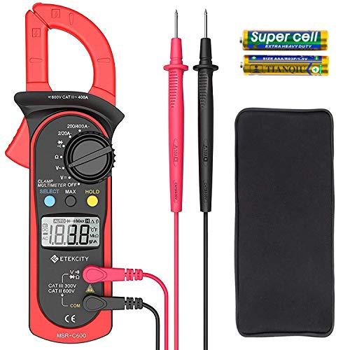
Accurately Measures: AC/DC voltage, only for AC current (not for DC current), resistance, and also provides diode and continuity testsJaw Opening: the Clamp measures the AC current in a conductor up to 26mm without interrupting the circuitAdditional Features: data hold, max reading, and an easy-to-read large LCDEasily Carrying: comes with a handy carrying pouch, perfect for use while you're on the goSleep Mode: automatically enters sleep mode after 15 minutes of inactivity for energy conservationBuy with Confidence: feel free to contact our California Support Team. We are always ready help if you have any question about our product.
And every garage I've been in has 1 compact fluorescent bulb. Buy a nice LED shop light or 2 depending on how big your garage is. Buy all the tools you need to wire it in like a nice set of Klein strippers and a cheap multimeter.
https://www.amazon.com/gp/aw/d/B000F9HIEC/ref=mp_s_a_1_4?ie=UTF8&qid=1495670572&sr=8-4&pi=AC_SX236_SY340_FMwebp_QL65
https://www.amazon.com/gp/aw/d/B00NWGZ4XC/ref=mp_s_a_1_9?ie=UTF8&qid=1495670627&sr=8-9&pi=AC_SX236_SY340_FMwebp_QL65&keywords=Multimeter&dpPl=1&dpID=417YqOjJ1mL&ref=plSrch
Cheap multimeters are fine for things around the house or troubleshooting most things on cars. You can also use the clamp yo measure current draw for some more advanced troubleshooting like seeing how much your AC compressor is drawing. If you do lots of tinkering with electronics I'd recommend dropping a few hundred on a Fluke.
No. Double the budget and come back.
-----
servers draw Oh, I dunno 700W each typically, but can triple that under serious load.
A typical switch needs right around 200W.
A PoE switch needs 200W plus the PoE load.
I have no idea what "6-7 other network devices" means.
But lets be kind of safe and call them 300W each.
Thats 6,100W of capacity using rough, approximate estimates.
So for that base load you're looking at about an 8kVA UPS unit like this one:
http://www.apc.com/shop/us/en/products/APC-Smart-UPS-SRT-8000VA-RM-208V/P-SRT8KRMXLT
He will run for 8 minutes at 6000W of load.
http://www.apc.com/products/runtime_for_extendedruntime.cfm
So we will need some extra batteries.
http://www.apc.com/products/runtimegraph/runtime_graph.cfm?base_sku=SRT8KRMXLT&chartSize=large
You're looking at two extra runtime battery packs like this one:
http://www.apc.com/shop/us/en/products/APC-Smart-UPS-SRT-192V-8-and-10kVA-RM-Battery-Pack/P-SRT192RMBP2?isCurrentSite=true
-----
So either:
Clamp that on a power cable, and it will tell you the amps passing through.
it might tell you the voltage too, or you will need to take a reading from an unused outlet using the two included probes.
Volts times Amps equals watts.
Total Wattage demand determines UPS size.
WARNING: devices use more power during boot-up than they do at idle.
Personally, at this size, I'd start thinking about a small Symmetra Frame like this:
http://www.apc.com/shop/us/en/products/APC-Symmetra-LX-8kVA-Scalable-to-16kVA-N-1-Rack-mount-208-240V/P-SYA8K16RMP
Yeah, its more expensive.
But it offers N+1 redundancy / high-availability, and it can scale up to 16kVA by adding power modules.
Check out a clamp meter. You would need to be able to get to the wiring near the breaker to measure the amp draw there.
https://www.amazon.com/dp/B00NWGZ4XC
There are also ones you can put between the outlet and item, but that only measures that item, not the whole load. It only works on 110v items (not an electric dryer).
https://www.amazon.com/P4400-Kill-Electricity-Usage-Monitor/dp/B00009MDBU
I was concerned about drilling any holes in my roof. Being a born pessimist, I figured if anything can go wrong, it will go wrong. The fewer holes in my roof the better.
I started looking for a roof rack. What I really wanted was a full-length roof rack with a diamond-pattern, "hardware cloth" platform surface upon which to mount my solar panels. All the racks I could find were around $600. Getting a rack custom built was estimated at $1300. Too much.
I finally found a very heavy-duty-looking rack made of black-painted round tubing for $311. "That's more like it," I thought. I ordered it off the internet.
When it arrived, I was annoyed to see that all the parts weren't there. Two long side panels seemed to be missing. I called the vendor, and after a very confusing conversation, it turned out that I had only ordered "half" the rack. The other part number was the side panels. Guess how much they cost? $300. ($611 for the whole rack. Dammit.)
Once I got the whole rack at my house, and started trying to install it, I realized that it's a two-or-three-man job. I finally got it installed, but Lord, what a pain in the ass!
I bolted a piece of 4x8 plywood to the rack tubing using large U-bolts. The PV panels bolt to the plywood.
I feel pretty sure that bolting the panels directly through the roof would work just as well, maybe better.
A really good book that describes solar panel installation is "Photovoltaic Design & Installation for Dummies" by Ryan Mayfield. He is the president of the Renewable Energy Associates solar power company.
A solid wire is called a "wire." A bundle of wires together covered with plastic insulation is called a "cable." You want cables of at least 6 gauge diameter. (The smaller the gauge number, the larger the cable. I know, it seems backwards.) A lot of solar power kits come with 8 gauge or even 10 gauge cable. TOO SMALL. Cable this small is inefficient for DC current, for our purposes.
You will need a "cable gland" (Amazon) and a good quantity of "Dicor self-sealing lap sealant." (Amazon). Be generous with the Dicor. Every time a cable goes through a steel bulkhead or floor you MUST put a grommet of some kind (rubber, plastic) there to protect the cable insulation. If you ground out a positive cable, it could cause a fire. Ground the negative (black) cable of the system TO THE VEHICLE'S FRAME, directly to clean steel (NOT PAINTED STEEL), through the floor. Bolt the ground cable connection securely to the frame. Don't forget the grommet.
https://www.amazon.com/Link-Solar-Weatherproof-Project-Campervan/dp/B0111RNZDY/ref=sr_1_2_sspa?ie=UTF8&qid=1506480381&sr=8-2-spons&keywords=double+cable+gland&psc=1
https://www.amazon.com/Scosche-WPG8-10-Gauge-Waterproof-Grommets/dp/B00OYGLP32/ref=sr_1_12?ie=UTF8&qid=1506480517&sr=8-12&keywords=8+gauge+cable+grommet
https://www.amazon.com/Auto-ranging-Multimeter-Resistance-Capacitance-Frequency/dp/B01N014USE/ref=sr_1_14_sspa?s=automotive&ie=UTF8&qid=1506480598&sr=1-14-spons&keywords=clamp+style+multimeter&psc=1
https://www.amazon.com/dp/B00NWGZ4XC/ref=dp_cerb_2
Always use BLACK cable for the negative (ground) side of the circuit and RED cable for the positive side. This will prevent you from screwing up and short-circuiting your system. Hopefully.
Do not hook up the PV panels until everything else is installed and you have tested it for continuity with a digital multimeter (DMM.) The kind that has a "clamp", automatic ranging, and an audible alarm is best. (It looks kind of like a lobster claw and doesn't necessitate puncturing the insulation of the cables.) You start wiring from the storage battery bank and work backwards to the PV panels. Keep in mind--if those panels are exposed to the sun, they are GENERATING ELECTRICAL CURRENT POTENTIAL. Cover them with cardboard or heavy paper and tape until you are ready to energize the system. You don't want to get electrocuted accidentally. The risk of shock is small, but it does exist.
You need either a fuse (good) or a DC breaker (better) between the positive cable between the PV panels and the charge controller, and also between the charge controller and the battery bank. If you install an inverter, you need a breaker on the positive cable between the battery bank and the inverter. (Inverters burn amps just sitting there hooked up. You need to be able to "turn off" the DC power supply to the inverter. Turn the power to the inverter back on to use it.)
https://www.amazon.com/MidNite-Solar-Photovoltaic-Circuit-Breaker/dp/B004EQK8SA/ref=sr_1_7?s=automotive&ie=UTF8&qid=1506481155&sr=1-7&keywords=DC+breaker
Try to make the cable runs as short and direct as possible, within reason. The longer the cable run, the more resistance and the more voltage drop. All cables should be secured to the bulkhead with cable clamps in a neat, tidy, workmanlike fashion. If it's worth doing, it's worth doing correctly.
Here are things from my wishlist (past and present)
Wera Screwdrivers
https://smile.amazon.com/dp/B0085NTQJK/
Oscillating blade set:
https://smile.amazon.com/dp/B0109SELWA/
Clamp multimeter:
https://smile.amazon.com/dp/B00NWGZ4XC/
Kreg Jig Jr.:
https://smile.amazon.com/dp/B000J43A7W/
Angled Long Nose Pliers:
https://smile.amazon.com/dp/B00N3VSS4S/
Groove Lock Pliers:
https://smile.amazon.com/dp/B000FK1R0W/
11 ft wifi endoscope:
https://smile.amazon.com/dp/B01MYTHWK4/
non contact voltage tester:
https://smile.amazon.com/dp/B001UAHZAM/
claw nail puller:
https://smile.amazon.com/dp/B0015YPJMY/
Workmate portable work bench:
https://smile.amazon.com/dp/B000077CQ0/
Cable snake fish tape:
https://smile.amazon.com/dp/B000BP7WBO/
9 Outlet metal power bar:
https://smile.amazon.com/dp/B00F8ZQY5M/
Spade drill bit set:
https://smile.amazon.com/dp/B00099E7WE/
36" bubble level:
https://smile.amazon.com/dp/B000UKMWMO/
There is a link in the FAQ on the page for how to do this. If it's an AC device (plugs into a household wall), then the most accurate thing to do is buy a Kill-a-watt meter and actually measure it.
Most devices list their max power draw, either in watts or amps. If it's in watts, just plug that into the calculator. If it's in amps, we have the converter at the top of the page to get the watts. If you can't find the power listed on your device, but own the device, you can get an ammeter (like this one) and measure as it's being used.
Instead of flipping each breaker for an hour, try this. Get a multimeter that tests amperage. Something like this:
https://www.amazon.com/dp/B00NWGZ4XC
You'll have to carefully remove the panel cover from your circuit breaker panel. Set the meter to amps and put the clamp around the black wire coming off each breaker. You'll be able to tell pretty quickly what circuit is using all the power, and you won't have to shut anything off.
Tl/Dr: video of what i just wrote out (video is not mine as I would start at the wall first. I had that beaten into me as an apprentice)
first invest in an inexpensive meter. heres an auto ranging clamp meter
then test the outlet. going by this pic check Line to line it should be 240v then line to neutral and line to ground 120v on both lines. and ground to neutral 0v
if all is good with the outlet, meter the connection on the unit the same way
l
I bought this one a year ago and I use it all the time, it's been great so far.
https://www.amazon.com/gp/aw/d/B00NWGZ4XC/ref=mp_s_a_1_3?ie=UTF8&qid=1500249073&sr=8-3&pi=AC_SX236_SY340_QL65&keywords=etekcity+multimeter&dpPl=1&dpID=417YqOjJ1mL&ref=plSrch
Anything like this, also referred to as a clamp meter:
Etekcity Digital Multimeter, MSR-C600 Auto-Ranging Clamp Meter https://www.amazon.com/dp/B00NWGZ4XC/ref=cm_sw_r_cp_apa_i_W9eQCb7BVGEM3
You run it over one half of a circuit to see the real time usage. For most devices you just grab one of those flat extension cords and carefully separate the insulated wires, or clamp it over the wires in the breaker box.
OLA is Open Lighting Architecture .. lets you convert one type to another .. but generally it has an ArtNet interface and lots of fun output interfaces including SPI. For some thoughts: last year I built 4 4'x8x16' steps we used on stage. We drove them with SPI Controllers .. that worked great .. but was expensive. The reason I went pi is the pi itself is $35 and built in wireless .. fadecandy is $22 .. can drive a pixel set of 64x8. This year we're building 12 steps 8'x8"x9" with 6 rows of 64 px driving off the QLC. I have githubs of the ansible code I use for all of this .. happy to share.
Some things to consider:
Please feel free to reach out any time .. do lots of work in this space and always willing to help ;)
Sorry lots of electronics technical stuff I just spat out there... this video might help
https://www.youtube.com/watch?v=HWA9WqSEjg8
The issue is it's a bit of "chicken and egg" problem, you need a powerful enough supply (high enough amp output) to make sure the load has as many amps as it will draw if the power supply can't supply enough current then your current you measure will be that limit instead of what the device actually wants to draw. If the power supply isn't able to supply enough amps for a given load (a device drawing current like the raspi) then it may overheat or shut off to protect itself or switch on and off depending on the power supply design.
Regarding a bench power supply this video shows how to DIY and compares with bought version and shows how they work:
https://www.youtube.com/watch?v=wI-KYRdmx-E
Basically any multi-meter can measure voltage and amperage:
https://www.amazon.com/Etekcity-Multimeter-MSR-R500-Electronic-Multimeters/dp/B01N9QW620/
For higher current stuff or measuring AC current without hooking the meter physically into the circuit can use a clamp meter like this instead:
https://www.amazon.com/Etekcity-Multimeter-MSR-C600-Auto-Ranging-Multimeters/dp/B00NWGZ4XC/
^^ second one also does auto-ranging so it works out what the right unit is to show you is based on the power going through it (shows mV or V or A and mA or milli-ohms, ohms, kilo-ohms, and mega-ohms depending on what you're measuring)
A simpler video just covering the whole concept of "load" and current here too (youtube suggestions did a good job)
https://www.youtube.com/watch?v=cxkVxi9P0EA
Multimeter
There's proper voltmeters that can test it better than just a pen. I got this one.
Etekcity Auto Ranging Clamp Meter, Digital Multimeter with Amp,Volt,Ohm,Diode and Resistance Test https://www.amazon.com/dp/B00NWGZ4XC/ref=cm_sw_r_cp_apa_i_NLKtDbMQ00KZ3
For anything that plugs in, you can use a smart plug like this to track its energy usage. For anything hardwired, you could use a meter with a clamp like this to measure instantaneous current.
So with the plug, rotate it around the biggest appliances in the house. Keep the fridge plugged in for a day, see what the average draw is, etc.
But you are right that heating/cooling is likely to be the culprit. The clamp meter will help you gauge its impact. Despite how it seems though, a 1990's air conditioner isn't dramatically less efficient than a new one...assuming it's in good working order. Make sure the condenser outside is all clear, no leaves piled up against it, dirt clogging the fins, etc. Then inside, follow the ducts wherever you can to make sure nothing came disconnected and is dumping conditioned air into you attic or something.
If it helps as a point of reference, our 2,400 sf house has central air from the 80's that is set for 75 when we're home and 82 when we're not, and our power bill for the July-Aug cycle when we were using AC consistently was $104. We're in coastal New England/ag zone 6b.
Then as the other commenter mentioned, your power company may offer free energy consultations where they come test your house for efficiency in a variety of ways, give you free LED bulbs and programmable thermostats, and make recommendations for how to reduce energy use.
Yeah you even said that you changed it... My bad.
To the onboard diagnostics, there is no real difference between a magic box (sensor) and the magic pathway going to it. What kind of line goes to the sensor? Is it just a regular wire? Coax type line? Something else fancy? Do you have a multimeter? If so can you disconnect both ends and check resistance (ohms) through the wire?