 Reddit reviews SIM&NAT 12inch / 30cm 40 Pin Male to Female Dupont Wire, 40 Pin Male to Male, 40 Pin Female to Female Breadboard Jumper wire Ribbon Cables kit for Arduino Raspberry Pi 2 / 3 (120 PCS)
We found 4 Reddit comments about SIM&NAT 12inch / 30cm 40 Pin Male to Female Dupont Wire, 40 Pin Male to Male, 40 Pin Female to Female Breadboard Jumper wire Ribbon Cables kit for Arduino Raspberry Pi 2 / 3 (120 PCS). Here are the top ones, ranked by their Reddit score.
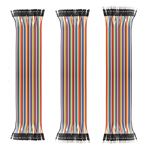
Length: 30cm/11.8 inchThe pitch of each end of the wire is 0.1 inch (2.54mm)40 pin jumper Wire are easy to separate from the ribbonSuitable for Arduino breadboard kit project, PCB project, PC motherboard, DIY experiment, 3D printer and etc.Package content: 1 * 40 pin male to female jumper wires, 1 * 40 pin male to male cable and 1 * 40-pin female to female cable (total 120pcs)
You can use any male to female ones, they're not special. Something like this should work fine.
I have my stock filament sensor wired directly to my RPi. I bought these cables from Amazon and soldered them together to get 36" length so there's enough slack as Z rises. It works with OctoPrint and the "Filament Sensor Reloaded" plugin.
This may be helpful:
https://www.youtube.com/watch?v=j7JfQXTf16U
Your stepper motors will plug directly in. You'll have to experiment with which direction the connectors go on. You can't damage anything if you get them wrong, so don't worry too much about it. You CAN damage things if your stepper controller current is too high, so make sure to check that before you start.
The endstops connect to X- and Y- on the white connector strip. They should share a common ground that you can just connect to any ground (the black strip.) I just used regular jumper wires like these.
You pull 24v and ground for the blue terminal block from the power supply's white 4 pin connector. The power supply board is labeled, so it's not hard to figure out what's what. You can cut the original connector and reuse it, or build a new one. The connector body is A19952-ND and the pin sockets are A19991CT-ND. I got mine from Digi-Key.
Here's where it gets weird. You need to invert the laser control signal from the Arduino to the L pin. I built the circuit on this page, although you could use an inverting optocoupler I suppose. The L pin, handily enough, is on the same white 4 pin connector as the 24v. GRBL 1.1 changed the laser output to a different pin, so your laser output will come out of the pin labeled Z+ on your shield.
I think that's everything I did with regard to the controller. Let me know if you've got any other questions.
 
edit: You might have a different PSU than I do, so none of this will make sense. In that case, read this.
I decided to do PWM. If I use a transistor I won't need a heat sink, right? Will I need any capacitors?
these are the parts I've found so far (Other than motion sensors, short jumper wires, and other common items)
Transistor \
Relays/ One or the other, transistors preferably
Wires
Nano Every
Breadboard(s)
Barrel Jack
Soldering Iron
Solder
Lights + Cable - Would the cable work with the barrel jack to provide power for the Nano Every and the LEDs?
Potentiometers