Best current sensors according to redditors
We found 11 Reddit comments discussing the best current sensors. We ranked the 6 resulting products by number of redditors who mentioned them. Here are the top 20.
We found 11 Reddit comments discussing the best current sensors. We ranked the 6 resulting products by number of redditors who mentioned them. Here are the top 20.


That's totally doable, it's just that the learning curve is steep if you aren't already familiar with micro controller projects.
I am sure that raspberry pi will work for this, but I am familiar with arduino type things so that's what I would start with. A "node mcu" controller has the wifi capability, then you will need a few current transformers like this, and a couple analog to digital converters (because the node mcu only has 1 analog channel)
Found it on Amazon.
Might not even be able to buy just the CT for that price.
Here's the solution that I used. I put the common wire for the furnace blower through a split core current sensor switch that controls the duct booster fan. Has worked flawlessly for the last 3 years. I used a Functional Devices RIBXGHTF. It has 120V AC terminals - making control of the booster fan really simple. Around $40 on Amazon, but I'll bet you can get it cheaper elsewhere.
Suncourt SW100 Current Switch https://www.amazon.com/dp/B003ZZDLQM/ref=cm_sw_r_cp_apa_221DAb2SVSS6J
If the thermostat thing doesn't work out for whatever reason then maybe this will help. You have to run the hot wire of the outlet that the electronics are on through the hole which acts as the switch for the fan.
The best kind of sensor would be a current clamp like this one, but I haven't tried it they're a little pricey and you'll have to split the power cable to put it over only only lead (if you put it around the entire cable, the two current fields will cancel out and you'll always read zero).
https://www.amazon.com/Suncourt-SW100-Current-Switch/dp/B003ZZDLQM/ref=sr_1_1?keywords=Suncourt+SW100+Current+Switch&qid=1568744855&s=gateway&sr=8-1
With such a lot of power and such a huge step down I'm not sure I'd be connecting a shunt directly to the Arduino and neither a voltage divider.
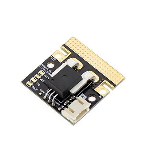
By preference I'd use something like this (https://www.amazon.com/DFROBOT-50A-Current-Sensor-AC/dp/B0187AAOMS).
>AC current transformer
So would i use something like this https://www.amazon.com/Current-Transformer-DROK-Transformers-Sensing/dp/B01LWN37KS? If so what would i connect to the wires? I haven't heard of using that before but my understanding is you run the cable through the inside of the hole. Then it outputs a measurement of how much is running through that cable.
After running the cable through the current transformer and getting the output signal. Would i then run that to 1kohm resistor. Then send that to an arduino?
How would i get the 1000:1 ratio? How do i bias the resistor?