Best electronic component sensors according to redditors
We found 125 Reddit comments discussing the best electronic component sensors. We ranked the 71 resulting products by number of redditors who mentioned them. Here are the top 20.
We found 125 Reddit comments discussing the best electronic component sensors. We ranked the 71 resulting products by number of redditors who mentioned them. Here are the top 20.


As someone who just finished a semester project with an Arduino and a Hall Effect Sensor, this is brilliant but the sensor would have to be installed in-line with either the water intake pipe or underneath the drip tip where the coffee filters into the pot.....our issue was there wasn't enough pressure to get the wheel to spin fast enough to register a pulse, so this isn't that trivial.
For reference, here is the sensor I used. I can link the Python code if anyone cares.
Or they bought one of these, this, and this, and now you have all the sensors for your spacecraft.
Some newer cars have infrared lights shining forward to assist collision prevention systems. I’d be worried about interference when parking near a vehicle with those systems.
Check this out. It actually looks like the type of ultrasonic sensor some cars with parking assist systems have in their bumpers.
Here is the main website detailing how to build an EDTracker. You should make sure to read through this website in addition to reading my comment.
You have a few decisions to make:
*****
Here's what I did for my build:
*****
After you build the EDTracker, it requires programming and calibration. I would follow the instructions from the website above, I don't have anything to add to those instructions.
In order to make the EDTracker software work with VRidge, you'll need OpenTrack to translate between the two pieces of software. Follow the instructions here to setup the EDTracker software and OpenTrack. You'll also need to set VRidge to take sensor data from the FreeTrack protocol.
There's one very important piece of information that doesn't appear anywhere. You want to start OpenTrack immediately after the orientation has been reset in the EDTracker software. That way OpenTrack will have the same understanding of the neutral position as the EDTracker software. If this isn't done correctly, you get really strange side effects when moving around. If you then want to map a keyboard button to reset the orientation, this should be done in the EDTracker software and not the OpenTrack software.
Hopefully you find this helpful!
Yeah. These:
https://www.amazon.com/gp/product/B07D6HYYSN/ref=ppx_yo_dt_b_asin_title_o07_s01
Paired them with an ESP8266 running ESPHome.
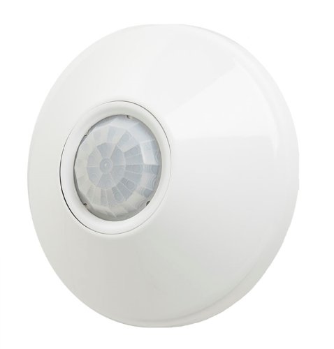
Occupancy sensor to turn off the lights or control HVAC
https://www.amazon.com/dp/B004QXKDYK/ref=asc_df_B004QXKDYK5247486
Optical sensors that I bought off of amazon:
https://www.amazon.com/gp/product/B00XT0PBC0/ref=oh_aui_detailpage_o09_s00?ie=UTF8&psc=1
They work flawlessly. Their max sensing distance is probably a little more than 1/2", so the balls have to pass fairly close to them. I ordered some blaze orange balls and they work perfectly with those. Then I ordered a set of lime-green balls and for whatever reason, those balls do not trip them AT ALL. I haven't yet found anything else that doesn't trip them.
Yes, electronics can cost a lot, and many of the telescope manufacturers make things, that when I look at them belong in the 1990s or 2000s, in terms of the way they work, and honestly could have been $400. It's basically the TI calcuator system: https://xkcd.com/768/
People have replaced those control systems, using technology (especially things like improved stepper control) which has come about for various reasons, like 3D printers, and simply faster microcontrollers.
Here's one: https://www.youtube.com/watch?v=tCBgmgc8qiA conversion (I suspect based on that it was using one of the faster controllers, but mine can do fine with an Arduino Mega + Ramps (the cheap controller))
So At 408 + a bracket (Easy and simple 3D print or easy to DIY, look at the OnStep Showcase for a number of them.)
Along with a 1/4-20 screw and a dovetail (Oh look: https://www.thingiverse.com/thing:2039785) , and you've got all of the functionality of a one of the Star Adventurers, along with the ability to mount pretty much any telescope up to 8" with a vixen dovetail.
Plus, unlike from what I can tell of almost all commercial ones, they don't seem to compensate for misalignment when tracking. (Ie, they only move RA, not DEC, unless guiding.) Here are some examples of unguided long exposures with dual axis compensation. (Also, He doesn't usually process them, these are per other discussions straight off the camera) https://www.flickr.com/photos/11381732@N08/albums/72157683118306836
Though that uses PEC (Periodic error correction, because worm gears often have high/low spots, so it can be corrected by basically guiding a few times and storing the corrections, which are then replayed). If you want that stored, which isn't included on what I mentioned above, but can be added for the cost of a magnet or two and a hall sensor ( https://www.amazon.com/WINGONEER-Effect-KY-003-Magnetic-Arduino/dp/B06XHG9CYN/ $8 and magnet https://www.amazon.com/Personalized-Multi-Use-Whiteboard-Magnetic-Refrigerators/dp/B075PMV2BC/ $8 ) Otherwise you'd have to retrain it each time.
One thing is that the microcontroller and drivers aren't the most advanced, but you can upgrade them if you want. (STM32 about 3x as fast, but it's rarely needed, except for better alignment is about $60, but add two drivers, so call it a net of +$40 extra but that the kit adds wifi ($6 and a bit of wiring to the original) and a hand controller to it. the faster processors ESP32 and Teensy cost more but are something like 14x as fast allowing better alignment. Mind if you use Howard's Sky Planetarium, it won't matter too much, and it'll be able to process on the computer.)
All new, and unless you have space taken up as your main concern the above setup is in pretty much all respects better than that suggested by dan.
Maybe I didn't describe that well. Someone flushes the toilet, and the water in the tank drops. The water sensor opens. When the tanks fills up again, the sensor closes (detects the water) and then fires another relay one time to inject the solution, not into the tank, but the bowl itself.
The next flush, the water drops, sensor opens.....
I'm assuming here that the sensor is in a closed state if it is in water. I suppose a floating bob switch might work too.
EDIT: Do you think these might work? I'm not sure how the trigger.
http://www.amazon.com/uxcell-Pieces-ZP4510-Vertical-Switches/dp/B00FHAEBIA/ref=zg_bs_306931011_1#Ask
I had done something similar. DIY stuff - JSN SR04T waterproof ultrasonic range finder along with a nodeMCU (ESP8266) . The sensor is fixed on top of the barrel and twice a day it measures the distance to the water level. You should Mount it about 20cm above the max. water level because that is the minimum distance it can measure. You will need microcontroller to calculate waterlevel. Here is an arduino tutorial to get you started.
Basically, I bought a float switch like this http://www.amazon.com/Aquarium-Water-Control-Plastic-Switch/dp/B005FDT02Q/ref=sr_1_6?ie=UTF8&qid=1406740109&sr=8-6&keywords=float+switch and clipped it to the rim of my tank so that it activates when the water gets higher than it should under normal operation.
There are a lot of different ways to wire it up so it shuts off your pump. Perhaps the simplest would be to connect the float switch to a relay that controls pump power. In my case, I have a custom built reef controller that I made using a Raspberry Pi. It does a whole bunch of stuff, including monitoring levels, temps, Ph and texting me when issues arise. It was relatively easy to wire the switch to the Pi and modify my program to shut off the pumps if overflow was detected. It also says "Main tank overflow detected, shutting down pumps" in a cool robot voice ;)
I built some custom scales using scrap hardwood and an HX711 AD converter and four 50kg load sensors for each scale. I'm running a very buggy and slightly modified version of tatobari's hx711py library on the raspberry pi to pull weight settings, but the readings are very shaky and extremely sensitive to changes in temperature, so it's only accurate to about +/-5% (which I'm comfortable with now). I have hardcoded tare weights for full and empty kegs/CO2 canisters, so the python script is sending a calculated percentage to the influxdb database (housed on another, more stable machine in my house) using the influxdb API.
My solution is a little janky but it came together quickly with tools that I'm familiar with. Other folks on r/homebrewing have come up with similar methods and PLAATO just introduced a commercial solution for weighing kegs.
This was actually fairly easy to setup and only cost about $8 and 30 mins of my time.
First you need to order an Inductive Sensor:
https://www.amazon.com/gp/product/B008FZC8F2/ref=oh_aui_detailpage_o01_s00?ie=UTF8&psc=1
Then I printed out a new sensor mount and glued it right next to my hot end.
Then in the Marlin Firmware, I enabled the auto bed leveling code and flashed the Arduino board. Next I set the boundaries of my bed and where I wanted the sensor to check. All you have to do is twist the sensor up and down to adjust how close the hot end is to the bed. After the sensor was mounted, you just plug the brown wire to +12v and the blue wire to ground. The Black wire goes to the signal pin on the z-min endstop. Supposedly you need to solder in some resistors inline (the youtube video below explains it) to lower the voltage being sent to the ramps, but mine works fine without the modification.
Now I never have to worry about the nozzle being to close / too far from the bed...
Here's a great youtube video that helped me get it all setup:
https://www.youtube.com/watch?v=EcGFLwj0pnA
They have waterproof ones, I made a similar parking sensor using this one:
diymore DC 5V Waterproof Ultrasonic Distance Sensor Measuring Ranging Transducer Module with 2.5M Cable for Arduino https://www.amazon.com/dp/B01J5KZU8M/ref=cm_sw_r_cp_apa_i_vu5UCbQ64NZTE
I can shoot you the code if you want.
Here you go, if 2mm detection distance is okay. Prime shipping~
The best kind of sensor would be a current clamp like this one, but I haven't tried it they're a little pricey and you'll have to split the power cable to put it over only only lead (if you put it around the entire cable, the two current fields will cancel out and you'll always read zero).
I will have these tomorrow: https://www.amazon.com/dp/B00ATNJH20/ref=cm_sw_r_cp_apa_3VSNAbF12C59J
Use a capacitance sensor. Same price but senses anything. 1-10 mm adjustable sensor is $7.35 on Amazon. http://www.amazon.com/gp/product/B00542U3M4?psc=1&redirect=true&ref_=oh_aui_detailpage_o05_s00
> might they be moving too quickly for a break beam IR or photoresistor?
A photocell will respond plenty fast. To get the Arduino to respond quickly enough use a digital photocell or obstacle detector module connected to interrupt-on-change pins, either on Arduino pins directly or via an IO expander like the PCF8575.
I'm interested in the same thing. I've only gone as far as to install one of these to get alerts on water level:
http://www.amazon.com/Aquarium-Water-Control-Plastic-Switch/dp/B005FDT02Q
I have a sump though so it's probably much easier to put one down there than on the top tank.
Everything he said is spot on. I have 4 cheap Chinese printers and those are all the recommended upgrades regardless of the brand.
I recommend this power supply. It can provide 50% more power and has a cooling fan.
These mosfets have worked very well for me and lowered bed heating times significantly as well as make your printer a lot safer.
Personally I haven't had any issues with the bed connector, but maybe some epoxy or hot glue would keep the wires from moving around too much.
One of the best upgrades I did was to flash Marlin onto the board as the stock firmware is kind of crappy.
This also allows the use of a Inductive proximity sensor which makes leveling the bed significantly easier.
The bearings he recommended, the Drylin ones, will make the movements of your printer a little smoother and a lot quieter.
The belts stretch. The ones from China are rarely reinforced. I'm lazy so i just tighten them every so often. But it would be worthwhile to just start with the higher end reinforced belts.
That aside, once your printer is up and running and somewhat calibrated, head over to thingiverse and search for your printer. There are thousands of upgrades available.
Good luck!
Amateur here, but I've used https://smile.amazon.com/dp/B008FZC8F2 for my 3d printer. This won't work?
I had to buy this bed sensor before I got a good level.
URBEST 8mm Detecting Distance Approach Sensor Inductive Proximity Switch NPN NO DC 6-36V Cylinder Type https://www.amazon.com/dp/B01M1777XK/ref=cm_sw_r_cp_apa_i_XcBtDbJDC8Y2P
Not quite. The board I have (which is fairly common) has two pins for trigger/echo. I've wired them together. So I write HIGH out then LOW then read it back. I presume writing to the ECHO pin does nothing.
Indeed on my board it works just fine. I can read distances and actually compare them to a ruler to get somewhat precise results. I mean even with two wires it's hardly a super precise mechanism anyways.
edit: To add... the boards I'm talking about are things like this. It has a speaker and a mic with a little control circuit to trigger the echo pin only if the signal is received. The trigger comes in one pin and the echo leaves another. In my "1 wire" setup they're simply wired together. So I'm setting the "echo" pin high but that doesn't appear to do anything negative.
If you do end up needing a replacement. This is the one I got. Works great and not too bad of a price. https://www.amazon.com/gp/product/B00DUYSWXK/ref=oh_aui_detailpage_o01_s00?ie=UTF8&psc=1
I am also using a Anet. the A8[ with this Sensor.] (https://www.amazon.com/gp/product/B008FZC8F2/ref=oh_aui_detailpage_o02_s00?ie=UTF8&psc=1)
I was also [following this video] (https://www.youtube.com/watch?v=G-TwWfUzXpc) But several things didn't work right.
I shall try what you did right now and see what happens.
I'm using the LJ18A3-8-Z/BX that was suggested in this Instructables. The problem I'm having is with the placement of the sensor. I first designed this bracket that mounts on the X carriage above where the filament cooling fan mounts. It fits nicely and is fairly close to the nozzle. The problem is if the nozzle contacts the bed first the whole carriage rotates up. This rotation cause the sensor to lift further away from the bed, which drive the nozzle lower... I'm going to design a new bracket that will attach to the linear bearing block. This will have the opposite effect if the nozzle impacts the bed. The sensor will be driven lower which should trigger the sensor sooner.
EDIT: Also, since it is an inductive sensor the 8 mm range is for steel/iron. The range for aluminum is about 4.5 mm.
Alternative solution: https://www.amazon.com/Uxcell-Capacitance-Proximity-Sensor-Switch/dp/B00542U3M4
Doesn't require you to switch out your bed, works just fine with glass, PCB, aluminum, steel, your hand, whatever.
No, its PNP. Says so right on the sensor.
EDIT: Here is the link. http://www.amazon.com/Cylindrical-Inductive-Proximity-Approach-LJ12A3-4-Z/dp/B007Q813UA
https://www.amazon.com/gp/product/B01M1777XK/ref=oh_aui_detailpage_o00_s01?ie=UTF8&psc=1
I checked the voltage and it seems to be right.
4.5v when open
0v when closed
Alright, I finally got around to it. My switch is NO https://www.amazon.com/gp/product/B008FZC8F2/ref=oh_aui_search_detailpage?ie=UTF8&psc=1 and I changed these settings:http://imgur.com/Sd57MTu
https://www.amazon.com/gp/product/B00OPNUO9U/ref=oh_aui_detailpage_o00_s00?ie=UTF8&psc=1
I actually just ordered this inductive sensor from Amazon: https://www.amazon.com/gp/product/B01M1777XK/ref=ppx_yo_dt_b_asin_title_o00_s00?ie=UTF8&psc=1 . In the reviews someone used it with success on our machine and said it was a significant improvement. Looks like an easy install by cutting and splicing the wires near the sensor. Seems like many people have success with this.
​
I'll check out the tinymonsters firmware, that also seems to be pretty popular. Is there any functional difference? Or is it just better behind the scenes?
It's an inductive sensor.
https://www.amazon.com/gp/product/B008FZC8F2/ref=oh_aui_detailpage_o07_s00?ie=UTF8&psc=1
I have my blue wired to the negative(-) on the board, and the black goes into where the red is on the end stop.
Brown (NPN) 6-36v
Blue - Negative on the Anet board where 12v comes in for main power.
Black - wired into the red plug on the Z endstop.
My probe: https://www.amazon.com/gp/product/B008FZC8F2
I use a LJ18A3-8-Z/BX sensor and used this guide to set it up. I made a custom bracket that fits onto my custom entruder carriage. I find myself having to adjust the z-offset regularly and I'm not sure why. I don't know if my sensor is moving in the bracket or if the sensor is just that sensitive to temperature/humidity. Overall I like it and I think it is better than manually leveling the bed.
THANK YOU SO MUCH!! I am attempting to attach a flow meter (https://www.amazon.com/gp/product/B00HR6BTYQ/ref=ox_sc_act_title_3?ie=UTF8&psc=1&smid=A1THAZDOWP300U)
to an Arduino and gave it measure the amount of liquid that is going through it and display it on a liquid crystal display (https://www.amazon.com/gp/product/B019D9TYMI/ref=ox_sc_act_title_1?ie=UTF8&psc=1&smid=A2IAB2RW3LLT8D)
and have it display the amount of liquid going through as ounces.
If this is to much I understand but I figured this would be a great place to turn for help.
Certain sensors, like the HC-SR04 distance sensor, require very reliable, low-latency real-time processing in order to measure the echo time. Raspbian isn't a real-time OS out of the box, so measuring sound wave travel time isn't very practical without some hackery.
I personally have a distance sensor pointed at my sump tank to measure water level, and I have that hooked up to an Arduino that buffers data from sensors, and in turn I have that hooked up to a Raspberry Pi.
Also, as /u/icarus901 mentioned about sensors being consumables, definitely buy sensors in bulk.
As for the controllers themselves, I have them in Ziploc bags because I'm cheap :P
H-Bridge (for the UNO there are also shields)
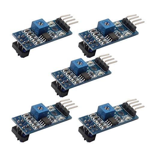
Sensors e.g. this / that though you can also get tctr5000 modules for cents elsewhere.
And note that if you are not set on a line-follower, the kit you've chosen already includes the ultrasonic distance sensor which is nie for robotic projects as well :-)
Do you have a soldering iron and multimeter? Even a cheap $4 multimeter is fine for low-current & low-voltage tasks, and makes your life easier (checking voltages, connections, resistor values...)
As for a soldering iron, even a $1 will do (if it doesn't burn down your house ;-) ) - but an adjustable temperature one will be more worthwhile. Even a $20 soldering station will do to get started if you don't want to spend $80-$100. I tried to avoid soldering for years, and it was a big mistake. It's actually easy and useful.
And another note: The 2wd and 4wd chars will not always go in a straight line. Motors don't run 100% in sync, even at the same voltage.
With a rotary encoder you can ajust the speed in software. You can use one of those IR reflective sensors modules, or a gap sensor, or even a hall sensor... example
You can also get 2wd kits example, but overall, they aren't as great of a value (and as you can see, they just include the standard modules)
A "sensor shield" like in that kit is nice though as it reduces the wiring chaos a bit :-) They cost $1 for the UNO at Aliexpress, probably more expensive at Amazon.
The circuit, washers, and fabric are decidedly more expensive than this, when all's said and done. They're somewhat similar if you're thinking in terms of just the actual hardware, but paying the employees that make sure the washers themselves are level first, and to assemble the more complicated system first is also a factor. This literally just screws into place.
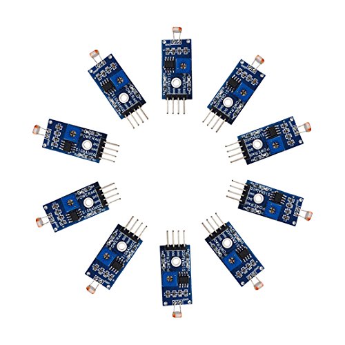
I found this 10 pack of light sensors on Amazon: https://www.amazon.com/Gowoops-Digital-Intensity-Detection-Photosensitive/dp/B01N1FKS4L/ref=sr_1_3?keywords=arduino+light+sensor&qid=1565710705&s=gateway&sr=8-3
Let's say I got these and attached them to each LED on the speaker splitter. Would I be able to attach 8 of them (mute LED and 7 zone LEDs) to the same microcontroller?
You want something like this.
https://www.amazon.com/dp/B00FHAEBIA/ref=cm_sw_r_cp_apip_Sr8bw6syd6DDq
I use it to make sure the reservoir for my plant watering device is full.
I've used these in the past for a non joystick related project:
​
Hall Sensor
This is for the Arduino starter kit.
This is just the distance sensor.
You can replace the sensor. This is courtesy of Jason Cook; sign up on facebook for the CR-10S user group and you can read his entire post there!
"Having trouble leveling the CR-10s Pro? Is the leveling sensor not repeatable and leaving you with bad first layers? Here is my solution:
URBEST 8mm Detecting Distance... https://www.amazon.com/dp/B01M1777XK…
The probe is extremely repeatable and does not seem to be significantly affected by temperature or humidity. I have mine set so that it detects the bed 2mm high and then the tiny Machines firmware remembers the offset on a power cycle. It nails the first layer every time and when probing the bed, the nozzle is high enough that it does not leave plastic dots on the bed. I was always having to tinker with the old sensor settings and had a lot of bad prints. Now, I just hit print and it works perfectly every time.
I hope this helps. I love printing with my CR-10S Pro now."
Like this, or this?
Occupancy Sensor.
Here is one on Amazon
https://www.amazon.com/Sensor-Switch-CMR-Contractor-Occupancy/dp/B004QXKDYK
To my knowledge, the most affordable option would to purchase an Inductive proximity sensor which purpose is to detect metal objects within a certain range.
http://www.ebay.com/bhp/inductive-sensor
http://www.amazon.com/Amico-Cylindrical-Inductive-Proximity-LJ12A3-4-Z/dp/B007Q813UA/ref=sr_1_1?ie=UTF8&qid=1381861724&sr=8-1&keywords=inductive+sensor
Just read you are using 12v to power the sensor. I have mine powered through the 5v+ sensor pin. I would not try this with the 12v unless you want to fry the board.
This is the sensor I believe i am using https://www.amazon.com/SMAKN-3-wire-Approach-Proximity-LJ8A3-2-Z/dp/B00NIAQLK2/ref=sr_1_9?keywords=inductive+sensor&qid=1570131253&s=gateway&sr=8-9
works fine on 5v
>AC current transformer
So would i use something like this https://www.amazon.com/Current-Transformer-DROK-Transformers-Sensing/dp/B01LWN37KS? If so what would i connect to the wires? I haven't heard of using that before but my understanding is you run the cable through the inside of the hole. Then it outputs a measurement of how much is running through that cable.
After running the cable through the current transformer and getting the output signal. Would i then run that to 1kohm resistor. Then send that to an arduino?
How would i get the 1000:1 ratio? How do i bias the resistor?
The ones I use claim a working range up to 4m. I've never tested them to that kind of range before though
https://www.amazon.com/Waterproof-Ultrasonic-JSN-SR04T-Integrated-Transducer/dp/B07FQCNXPP/ref=mp_s_a_1_3?keywords=waterproof+ultrasonic+sensor&qid=1573248470&sprefix=waterproof+ultraso&sr=8-3
Thanks. FigJam did all the work. I kinda tidied things up.
Amazon has a bunch of styles. Look for aquarium or transfer tank float switch. I used these but they tend to fail quickly or are DOA. Here is the straight version. You will need to fashion a mount or stand for them.
Others can post what they used.
an $8 inductive sensor also just plugs into the z-endstop, but you would have to solder the connection on yourself. https://www.amazon.com/URBEST-Detecting-Distance-Inductive-Proximity/dp/B01M1777XK
But if you want something plug and play get a BL Touch: https://www.amazon.com/BLTouch-Leveling-Sensor-Premium-Printer/dp/B01FFV2TOS
with all of these options you have to update and flash the firmware to enable and allow autoleveling.
What about the 24v? Are there any considerations for the increased voltage on the Tornado? Is there a picture somewhere I can follow so I don't fry anything on the MKS?
And how about this sensor, bueno?
I literally just bought these for the same purpose. They are on/off and work well. The vout needs a pill up resistor.
10 pcs New A3144 A3144E OH3144E 3144 Hall Effect Sensor https://www.amazon.com/dp/B00ATNJH20/ref=cm_sw_r_cp_api_TzkOAbDB2KAFP
No problem!
This
Look it up on thingiverse, too. Tons of mounts for it that you can print out. You'll see them on pretty much everyone's head.
https://www.amazon.com/Elegoo-HC-SR04-Ultrasonic-Distance-MEGA2560/dp/B01COSN7O6/ref=pd_sim_147_4?_encoding=UTF8&psc=1&refRID=TPBMW2PJ392W4FE64FX1
these should work too, if you find a way to make them more resistible.