(Part 2) Best electrical connectors according to redditors
We found 71 Reddit comments discussing the best electrical connectors. We ranked the 35 resulting products by number of redditors who mentioned them. Here are the products ranked 21-40. You can also go back to the previous section.


No problem. Take the hdmi cable out of the package. Strip about one inch of the black insulation away on both of the ends you cut. You should find 9 pairs of twisted cables. Fortunately they are color coded. Untwist the pairs. Strip 1/4 inch of the insulation off of each colored wire. Now using splice connectors put the corresponding end of each colored wire in the connector and compress it. Repeat for each wire. Now take some electrical tape and wrap everything. Don't be stingy on the tape. Should be good as new. You're welcome.
Sure!
Dein Username prüft übrigens aus.
The Light Units
The Chips x4: 98.6$
The Driver x1: 74.9$
CPU Cooler
x4: 55.96$
Thermal Adhesive Paste x1: 7.9$
4way pin for the coolers x1: 9$
Lights Total: 246.36$
Framing and stuff
Most guys build their framing out of aluminium profiles. I bought mine here from the %%% section: https://www.alu-verkauf.de/ALUMINIUM-ALUMINIUMPROFILE
Every country has its own manufacturers for these. Mine cost about 30$.
You also need cables. The veros are pretty flimsy. so take pretinned gauge x1: 9,95$
In order to screw the frame you might wanna cut holes swith a thread. This will do x1: 8.43$
Be careful these drills suck and break easily.
Screws x1: 12.98$
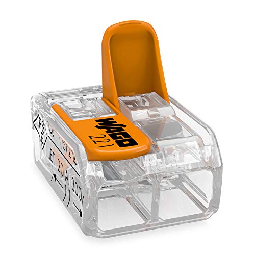
Wago Connectors
x1: 6.35;$
Were at about 315$.
Lets see what we can do with it.
my frame is build with 6 L-Profiles in which the COBs just lay around and one center piece: Link to Pic
You might additional hangers, cold device cables and another power source for the cooling fans. If you decide to buy the MeanWell HLG-320H-2100B you will need to connect a 10kOhm potentiometer to the Driver. This is to dim the light and safe money in vegphase. The HLG-320H-2100A has a build in dimmer which you can access via a screwdriver. I would recommend A, since its easier to operate. You can also regulate the fans of the cooler via a 150Ohm poti. If you dont like the sound, you can run them at 1/3 to 1/2 speed.
have fun!
They are Gardner Bender push in connectors.
Here is a link to the product on amazon - https://www.amazon.com/URANT-Intelligent-Household-Appliances-Smartphones/dp/B017H0WK2Q
Have you seen round cables with these 2.54mm header pin connectors premade?
10pcs 2.54mm 4Pin-4Pin F/F Solderless Jumper Cable Wire Connector 10cm https://www.amazon.com/dp/B0143YM5WO/ref=cm_sw_r_cp_api_jU32AbYQXMH9C
I wish I had a better answer for you but unfortunately that is just a bunch of individual FF jumper wires stuck to a MM header pin like this which is then soldered to the board. The opposite side that goes into the relay is just the loose jumper wires that fit onto the pins on the relay board.
I really really wanted a good connector solution so I could have connectors on the board that would make it easy to detach all the wires, preferably all in a single harness (or at most a couple harnesses). I didn't find anything that was simple and worked well. When I eventually rebuild this thing (which I plan on doing sometime), a better connection solution between the pi and various sensors/relay boards is one of the biggest improvements I want to make.
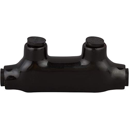
The disconnect is so I can remove the battery every time I take the boat out of the water (to bring it inside for a trickle charger, which means both negative and positive need disconnects)
I found these: https://www.amazon.com/NSI-M-CBL-Block-IPL1-0-3B/dp/B008KNL7WE
Does this work like I'm expecting? Thanks for the suggestion about power distribution blocks, I'll take a look.
It takes a lot of drinking but they fit into wine/liquor bottles with ip65 cable glands something like this: https://www.amazon.com/Black-Plastic-Waterproof-Connectors-Glands/dp/B00841YHHY/ref=asc_df_B00841YHHY/?tag=hyprod-20&linkCode=df0&hvadid=228763672776&hvpos=1o1&hvnetw=g&hvrand=3089221781606621095&hvpone=&hvptwo=&hvqmt=&hvdev=m&hvdvcmdl=&hvlocint=&hvlocphy=9002019&hvtargid=aud-801381245258:pla-392546892203&psc=1
Just drill a hole in the cork/cap to accomodate the gland and screw it on. Makes a cool fixture. Or string the together for some great outdoor or bar lighting.
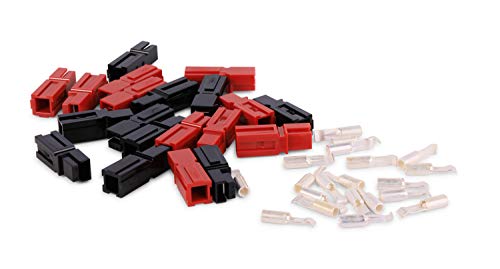
You could solder or use these. I've done LED lighting on vehicles and always use them.
https://www.amazon.com/Ideal-30-765-Twister-Wire-Connector/dp/B000BVMAZ6
https://www.amazon.com/King-Innovation-Port-AlumiConn-Connector/dp/B00EDQ1HLS/ref=cm_cr_arp_d_product_sims?ie=UTF8
You'll need to use something like this to make your splices.
What sort of butt splice are we talking?
Are these even NEC compliant?
https://www.pacergroup.net/nylon-butt-splice-8-4-awg/
This looks to be underground only:
https://www.amazon.com/dp/B001AWP7OG/
I was thinking more along the lines of this: https://www.amazon.com/dp/B00UKG81GO/
would these work?
so i wire the battery AND battery mount to the motor?
Yeah what the other guy said. 110. Can't believe I haven't seen one of these before myself.
Was expecting it to be some shitty token ring esq connector spec. But can meet or exceed cat five or CAT6 spec.
What is the use case for these connectors? Looks like online they are for connecting patch panels versus client to switch
http://www.amazon.com/Allen-Tel-Products-GB110-C6-4-Connector/dp/B005M1YQR0
That's where you need to very carefully hand dig then. Just follow that wire and you'll find the ground rod. It may be up to three or four feet from where the wire goes into the ground, but follow the wire and you'll find it. Be careful not to cut or damage the wire!
EDIT: Also wanted to note that while normally they aren't buried very deep, they can be if they were put in before the home's foundation was backfilled. You also have the option of attaching your ground wire to the existing one above ground using a split bolt connector - here is a picture of one but it may not be the correct size for your ground wire; I'd buy one locally so you can return it if it's the wrong size: https://www.amazon.com/Morris-90316-Connector-Conductors-Number-6/dp/B005GDFQS2 Just be careful not to damage the existing ground wire while making the connection.
Based on some of the good ideas I've seen here, I went product hunting.
What about something like this: https://www.amazon.ca/Gardner-Bender-FLX-538C10-Split-Combo/dp/B01NAWUM1J
It's a firmer plastic-style protector. I'm not sure if that would be better or worse than the braided cable protectors. I'm thinking better, because one of the key attributes is for the cable protector to resist a sudden bend radius that would cause a kink in the cable.