 Reddit reviews Etekcity Digital Multimeter, Volt Ohm Amp Meter, Voltage Tester with Continuity, Diode and Resistance Test, Dual Fused for Anti-Burn, Red, MSR-R500
We found 17 Reddit comments about Etekcity Digital Multimeter, Volt Ohm Amp Meter, Voltage Tester with Continuity, Diode and Resistance Test, Dual Fused for Anti-Burn, Red, MSR-R500. Here are the top ones, ranked by their Reddit score.
ACCURATELY MEASURES: This Multimeter can test AC/DC voltage, DC current (not for AC current), resistance, diode, continuity, and more. Sampling speed: 3 times per secondEASE OF USE: Data hold button holds a reading; Large backlit LCD with large digits is easily visible in dimly lit areas. Built-in support stand allows for hand free useSAFETY PROTECTION: Overload protection on all ranges. Protective rubber sleeve around the Multimeter adds extra drop protectionGREAT AFTER-SALE SERVICE: Lifetime support from our California-based customer support teamNOTE: This Multimeter cannot be used to test AC current! Please make sure the rotary switch is located at the right range during use
It looks like you have damaged contacts, may have caused bridges, and who knows what all else. If you want to attempt to fix it, I'd say you need to be prepared to spend a lot of quality time with at least a cheap multimeter or other circuit continuity tool in order to determine where circuits are failing when they should succeed and where they are succeeding when they should fail. And you should definitely be prepared to discover in so doing that the damage is indeed too extensive to make a repair worthwhile.
Given that, it may well be more prudent to accept that pcb as a write-off and begin disassembling and desoldering everything and buying a relatively inexpensive replacement pcb.
Mostly it comes down to how you want to spend your time.
If you want to hone your circuit troubleshooting skills, this is an excellent opportunity to get more hands on experience with digital electronics and learn quite a bit.
If you just want a working Ergodox as quickly as possible, then I'd say accept the loss and begin rebuilding now.
Try multimeter like this https://www.amazon.com/Etekcity-Multimeter-MSR-R500-Electronic-Multimeters/dp/B01N9QW620, you need to test voltage and grounding
Time to invest into a multimeter or Outlet Tester
People are hypersensitive about recommending DIY work on electrical on the internet. I get it, you have no idea who you're talking to and what they're going to do with the advice. But the same people have no problem giving advice for building structural elements, masonry work, or plumbing. Sure, you won't burn your house down, but it doesn't mean you can't destroy it.
Anyway, we're not talking about running wires, selecting gauges or making any significant wiring decisions. If the wiring is prepped properly this should be a straightforward exercise. Use your head, read the directions, turn off the breaker before hand, ask questions if you get stuck. I would recommend getting a cheap multimeter if you don't have one; always smart to double check the line is dead with a DMM before working. They're insanely cheap now, and every homeowner should have one. Here's one for $9.
https://www.amazon.com/Etekcity-Multimeter-MSR-R500-Electronic-Multimeters/dp/B01N9QW620/ref=sr_1_4?s=lamps-light&ie=UTF8&qid=1536552361&sr=1-4&keywords=voltage+meter
You might want to check the output of your controller just to make sure that the problem isn't deeper. Idk what anything is supposed to measure, but if you compare the z outputs to the x or y outputs it should be pretty easy to figure out if something is wrong. If you don't have a multi meter you can get a pretty basic one for ~$10. Or if you have good neighbors you can probably borrow one -- it is standard kit in most middle-aged men's toolboxes.
https://www.amazon.com/Etekcity-Multimeter-MSR-R500-Electronic-Multimeters/dp/B01N9QW620?ref_=Oct_BSellerC_15707471_1&pf_rd_p=2bd56caf-41c7-5afe-a16b-f91d83e8f5ca&pf_rd_s=merchandised-search-6&pf_rd_t=101&pf_rd_i=15707471&pf_rd_m=ATVPDKIKX0DER&pf_rd_r=RWEXC9AQXED7VJG8FQE0&pf_rd_r=RWEXC9AQXED7VJG8FQE0&pf_rd_p=2bd56caf-41c7-5afe-a16b-f91d83e8f5ca
https://www.amazon.com/Etekcity-MSR-R500-Multimeters-Electronic-Multimeter/dp/B01N9QW620/ref=sr_1_4?ie=UTF8&qid=1510104755&sr=8-4&keywords=multimeter
So something like this then?
Lol. Chuckle Butt has been in your same shoes before! Folks call it different things. https://www.amazon.com/Etekcity-Multimeter-MSR-R500-Electronic-Multimeters/dp/B01N9QW620
And then can test it https://itp.nyu.edu/physcomp/lessons/electronics/understanding-dc-power-supplies/
It's fairly common. Worth at least asking around.
Yeah, I have a multimeter.
I can swap 2-wire receptacles no problem, something about GFCI scares me- more wires to mess up, I suppose.
Gets me nervous to pull the outlet out and leave the power on- but I suppose I can test with the probes without removing the outlet from the box.
I've never tested AC power with my multimeter- just DC projects, but I imagine it is just anything on AC setting(s).
https://www.amazon.com/Etekcity-MSR-R500-Multimeter-Electronic-Continuity/dp/B01N9QW620/ref=sr_1_7?ie=UTF8&qid=1503503420&sr=8-7&keywords=multimeter
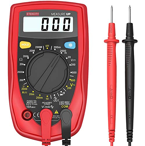
Using this guy, it'd just be the 200V setting on the top right
Ok, if you plan to build more, you don't have to invest a lot... AMAZON has some for under $15. Worth having around. The continuity testing is the setting above OUT and below 200 V~ on that model. It is about at 5 O'Clock. Others will have the same symbol somewhere. When a connection is made it beeps.
But yeah, that jiggling the cable and the keys work is odd. If you get a multimeter, you could also test each connection on the PM to see if there are any shorts between posts that are next to each other... sometimes if we are too generous with the solder it could flow between posts under the PM. Not common but possible. Odd it would be keys in different rows and columns if that is the case though... but these are the things I do to troubleshoot.... and don't feel too bad... even if you do everything right with these things there can be small issues that come up. I have a Gherkin right now that the bottom right 5 keys are not activating... they did work on my first flash and now they don't... I had just built it and tested it before putting the bottom plate on... once the bottom plate went on the bottom right keys stopped... I am hoping I just activated a layer toggle but I have not had time to troubleshoot it yet.
Did you try a different cable? The PM can be tight when new so sometimes it might feel like it is in all the way when it it not.
If none of that helps, can you post close ups of the PM from the top, and all four sides... try to make them as high res and clear as possible.
Get one that can check continuity. Continuity is continuous flow electrons through wiring. I bought this one for $10.
https://www.amazon.com/dp/B01N9QW620
You want to test the connections to the RCA terminations. RED and WHITE wires are the center post on the RCA. GREEN is the barrel of the connection on the Red RCA. Blue is the barrel of the connection on the White RCA. Specifically, you are looking for see if there is a short. This would be indicative of continuity being crossed in the wires. Specifically, hum will occur if you get cross polarity. So you should as an example, only have continuity from the GREEN wire to the barrel of the Red Connector. If you also have continuity to the post, you likely have a broken solder joint in the RCA. Or you have a broken wire in the tonearm. You are doing diagnostics, you'll have to use your brain to actually figure out the proper fix. I will state that terminating a new RCA plug to a turntables wiring can be tough. There are very small wires. You'll need a really good wire stripper for the positive wires. There are very few strands of wire in a tonearm conductor, so you really can't afford to break any of them. I've done it and I'm better at mechanical than I am at electrical stuff. So, it can be done. But you have to be patient. If you don't thing you have the right tool, it's good chance you don't. The wire is generally something like 30AWG. So look for a pair with 20AWG - 30AWG. Typically, house hold wire strippers only go to 18AWG. Don't even try to use ones you have lying around. The one's I've linked might work.
20-30 gauge wire strippers
Sounds like the powersupply is tripping. Most PSU's have a type of breaker in them to protect the system, this isn't usually tripped by wall power but by a power problem in the system itself. It is also possible if the power is really bad (brown outs) it is/has damaged the system. You can buy a multimeter pretty cheap from amazon or get one at walmart. https://www.amazon.com/Etekcity-Multimeter-MSR-R500-Electronic-Multimeters/dp/B01N9QW620/ $10 for voltage testing only. Also, are there high current items on the same circuit? i.e. High powered Microwave (1000w+), Air Conditioner, they can cause dips in the voltage that over time could cause problems.
My Etekcity has gotten the job done so far, definitely less than $40.
I'm a firm believer in the concept of buying a cheap tool until you wear it out (if you do). Wearing out a tool indicates the frequency with which you use it, and also that you need something built tougher to last longer. Once you wear out the Etekcity, go with a Fluke. As far as I know, they're basically industry standard.
Low voltage cut off feature, part of most hardwiring kits.
Step 1: Figure out if your dash cam is Mini USB, or Micro USB.
Micro USB looks like most cellphone chargers.
Mini USB looks like a box.
Step 2: Figure out what type of fuses your vehicle uses: Mini, Mini low profile common. Micro 2, Micro 3, ATO less common.
Tap a fuse, and all fuses should match your vehicle.
Step 2: Decide: Cheap or Expensive hardwire kit
Hardwire the dash cam to an ignition only fuse.
Do not use: Airbags/Ignition computer/Security system/Headlights/High voltage/Hard to replace/Safety/expensive parts.
Most hardwire to cig lighter (as it is often ignition only) or Ignition key.
There is a device: Fuse tester light ($6 USD) this can be used to identify always on, ignition only, fuses, or you could get a Multimeter ($9 USD) and do the same thing.
---
My personal opinion is Aukey is a bad copy of A119 variants. A119 has a specific hardwiring kit
A119 hardwiring kit ($10 USD) Which is superior to the cheap kit in some ways (able to use ignition coil to decide when on/off as it is 3 wire instead of 2 wire.
Sorry lots of electronics technical stuff I just spat out there... this video might help
https://www.youtube.com/watch?v=HWA9WqSEjg8
The issue is it's a bit of "chicken and egg" problem, you need a powerful enough supply (high enough amp output) to make sure the load has as many amps as it will draw if the power supply can't supply enough current then your current you measure will be that limit instead of what the device actually wants to draw. If the power supply isn't able to supply enough amps for a given load (a device drawing current like the raspi) then it may overheat or shut off to protect itself or switch on and off depending on the power supply design.
Regarding a bench power supply this video shows how to DIY and compares with bought version and shows how they work:
https://www.youtube.com/watch?v=wI-KYRdmx-E
Basically any multi-meter can measure voltage and amperage:
https://www.amazon.com/Etekcity-Multimeter-MSR-R500-Electronic-Multimeters/dp/B01N9QW620/
For higher current stuff or measuring AC current without hooking the meter physically into the circuit can use a clamp meter like this instead:
https://www.amazon.com/Etekcity-Multimeter-MSR-C600-Auto-Ranging-Multimeters/dp/B00NWGZ4XC/
^^ second one also does auto-ranging so it works out what the right unit is to show you is based on the power going through it (shows mV or V or A and mA or milli-ohms, ohms, kilo-ohms, and mega-ohms depending on what you're measuring)
A simpler video just covering the whole concept of "load" and current here too (youtube suggestions did a good job)
https://www.youtube.com/watch?v=cxkVxi9P0EA
check this out https://www.youtube.com/watch?v=5G622WDZaHg
I highly suggest you pick yourself up a cheapo multimeter if you haven't already, they're super handy for this hobby and will save you a lot of time troubleshooting electrical issues.
Im not exactly sure how X220 is wired but what you want to do is make sure the (usually) yellow wire that carries the feed from camera to VTX is unbroken.
Assuming your camera connects directly to VTX:
Basically put the probes on each side of the yellow video signal wire between camera and vtx. If everything is OK the multimeter will beep. If multimeter doesn't beep then that means the connection is broken and VTX is not getting the video signal from camera, and you should resolder or replace the wire entirely depending on the issue.
If you have some sort of OSD (or flight controller with OSD):
Test the yellow wire between camera(video Out) and flight controller(video In), and then the yellow wire between flight controller(video Out) and vtx(video In). And then check continuity between the video In and video Out on your flight controller to make sure the OSD chip didnt crap out.
If you did all of the above and multimeter is beeping in all cases and the video feed is still black then more than likely the camera is bad.
Etekcity Digital Multimeter, Amp Volt Ohm Voltage Tester Meter with Diode and Continuity Test, Dual Fused for Anti-Burn https://www.amazon.com/dp/B01N9QW620/ref=cm_sw_r_cp_api_i_58ooDb6BX0X3X
should this one do the job ? and are most wires connected to a fuse box or breaker box in the van? i assume that’s where i would disconnect them. the Van i have didn’t come with a manual so i wonder where it would be
I have a 88 Chevy g20 hightop