Best automotive electrical system relays according to redditors
We found 203 Reddit comments discussing the best automotive electrical system relays. We ranked the 94 resulting products by number of redditors who mentioned them. Here are the top 20.
We found 203 Reddit comments discussing the best automotive electrical system relays. We ranked the 94 resulting products by number of redditors who mentioned them. Here are the top 20.


![ONLINE LED STORE 6 Pack Bosch Style 5-Pin 12V Relay Kit [Interlocking Harness Socket Holder] [14 AWG Hot Wires] [SPDT] [30/40 Amp] 12 Volt Automotive Relays for Auto Fan Cars](https://m.media-amazon.com/images/I/51vqG7TADXL.jpg)


This is something that can be repaired without the risk of replacing the entire window.
https://www.amazon.com/Permatex-09117-Complete-Window-Defogger/dp/B000ALBZJY
This. One of those kits to paint on defroster wire traces for the back window. Resurected an apple keyboard from 2005 period that was half filed with coke. Basically repainted the left 1/4th of the entire membrane with a little vile from advance auto.
OK. Here is what you are dealing with:
1.(L) black. Line voltage load. Either 110v or 220v. Need to verify with a voltmeter.
2.(W/Y) orange. W=heating and Y=cooling. Used for a two pipe hydronic heating/cooling system. That means water.
3.(Y/A) yellow. Y = cooling. A = electrical heater output. Heat and cool active to any relay.
4.(G1) red. Low speed fan. Through a relay.
5.(GM) blue. Medium speed fan. Through a relay.
6.(GH) brown. High speed fan. Through a relay.
7.(N) white. Line voltage neutral. Either 110v or 220v. Need to verify with a voltmeter.
What is missing is the "C" and "R" wires. Nowhere is there a low voltage 24v load and common wire. Your current thermostat does not use it.
You have two options that I know of. Purchase a transformer to supply the 24v to your new thermostat. Or return the Honeywell and purchase a wifi enabled line voltage T-stat.
Transformers. Here are two that may work:
http://www.amazon.com/gp/product/B0037MXM1C/ref=ox_sc_act_title_2?ie=UTF8&psc=1&smid=A26RBB5XP2LWJC
For 240 volts
http://www.amazon.com/Honeywell-RC840T-120-Electromechanical-Relay-Built/dp/B00D5YLY2G/ref=sr_1_1?ie=UTF8&qid=1464560168&sr=8-1&keywords=Aube+RC840T-120
For 120 volts
Line voltage T-stat:
https://casaconnect.com/en/shop/smart-thermostat-caleo/
Note: Since you have hydronic heating and cooling, in addition to HVAC, either choice for the thermostat will likely mean that you will loose that option. I have not evaluated the new Honeywell or Casa to see if they support hybrid systems.
All I needed to do after converting my battery voltage to 12 volts was wire up a few switches and a blinker relay. Here is the tail light and blinker relay
Taillight: Greenclick 40W Motorcycle Tail... https://www.amazon.com/dp/B072Q5MK75?ref=ppx_pop_mob_ap_share
Blinker relay: AUDEW 2-Pin Electronic Turn... https://www.amazon.com/dp/B011BTMDQM?ref=ppx_pop_mob_ap_share
Yes, basically any standard 2 wire banana plug turn signals will fit in the front and rear. You will also need to get an led flasher. I have these on my front. This flasher relay should work.
No I've had multiple cars where the lines are obviously on the inside surface. They sell repair kits for rear window defrosters and obviously none of these kits would make sense if it was inside the glass.
That said, some higher end cars do integrate the lines into the glass these days but it's a mixed bag. You're less likely to have someone damage the lines by accident and thus less likely to need a repair, but if the lines do go bad over time you have to replace the damned rear glass (and they do go bad). Not sure which I'd rather deal with lol
I don't know about the Avalon specifically, but its possible in many cars. You'll have to exercise some Google-fu.
A whole bunch of factory head units, especially on nicer cars starting in the early 2000s, have aux inputs on the back of the unit. Before an aux input became a standard equipment expectation, it was often a dealer-installed option (i.e. plugging in and running an aux cable) or used to wire up a CD changer (which you can often unwire and replace with an aux in).
For instance, here's what I installed in my car: http://www.amazon.com/BMW-82-11-149-389/dp/B000PA00XM#productDetails. $36 on Amazon for OEM, or you can hunt around on eBay or other smaller sites and probably find an OEM one for $25 or a knock off for $15. Literally just plugs into the back of the unit, then you run it to wherever you want, but typically the glovebox is easiest.
Optionally, I also discretely mounted a small ~$40 bluetooth/A2DP receiver (this guy, much nicer than OP, gets power from the car and also doubles as a USB power plug) on the dash next to the stereo and ran its wire under the trim into the glovebox to connect to the 3.5mm aux. It works/sounds great and I mostly use the bluetooth since its nice to not have to fiddle with wires every time I get in/out of the car, but I can also unplug the bluetooth and plug straight in to the 3.5mm plug in the glovebox.
This is the polar opposite of SMD, but I thought I'd share my solution...
While I love DIY, smoke detectors are important. I wanted to interface with my home system but without compromising the integrity of the system.
Get a 120v first alert.
First Alert SA521CN Wireless Interconnected Hardwired Photoelectric Smoke Alarm with Battery Backup https://www.amazon.com/dp/B000EVO9D4
Get the smart relay interconnect.
BRK RM4 Smart Relay for First Alert https://www.amazon.com/dp/B0039PF21U
This includes schematic for wiring to the detector and the color codes for NO/NC relay connection.
~~Get an optocoupler or isolation relay. Mains Voltage! The output of the RM4 is 120V.
Enclosed AC/DC Power Relay with Protection & De-Bounce. Screw Terminals. 120V Trigger Input. https://www.amazon.com/dp/B017743I7S
The RM4 output powers the relay. The screw terminals connect to the 8266.~~
Get a Esp8266; Flash tasmota firmware. Configure for switch and mqtt. Wire it up.
First Alert is now part of the matrix.
Quick update: Did not need the second relay/optocoupler. The BRK RM4 is an isolated relay. Their docs did not make that perfectly clear so I assumed worst case w/o testing it.
I'm not entirely sure if you it will work in a 2004 or not but I installed this bad boy amazon in my 2006 325ci about two years ago and it still works like a charm.
Mud flaps - many use Rally Armour
Footwell lighting kit
And if her white 5-door isn't tinted, get it tinted.
I would think it's best to power the motors with a separate power supply from the Arduino power since the motors will draw a lot of current. Instead of powering the motors from the onboard 5v supply, run a separate supply through either a relay module or a motor controller board. Like these: relay, motor driver.
Do you have a cable box or any other device that makes heat 24/7? If so, you might consider wiring up the fans to run 24/7. That's also the simplest way to wire them. Lower temperatures are good for electronic longevity. Fans wear out in a few years, but are cheap to replace compared to a PS4 or receiver.
If you want to trigger them off your receiver, that's pretty easy to do. Most likely your receiver can't power the fans directly (most 12V trigger outputs are 200-500mA output). Some receivers have a switched 120V outlet on the back, which makes this really easy, you just plug the fans in.
Fans can draw anywhere from 160mA (0.16A) to 600mA+ (0.6A)
The Antec fan you linked doesn't have a spec listed for power draw, but typically very quiet fans are below 300 mA.
If your total fan power draw (add together all fans) is less than 90% of the power your receiver can output, you can hook the fans up directly.
If your total power draw exceeds 90% of the rated output of your receiver, you need to use a relay to power the fans.
Here is a relay board that will work.
Here is the same thing but shipped free (probably from China, may be slow)
You'd also need a 12V power supply that provides enough current to run all your fans together.
Here are USB Fans - plug straight into PS4 or TV, and they turn on when the device powers up.
You could also use a 5V relay to control 12V fans from the PS4 usb if you wanted. Or use the TV's USB to trigger the fans whenever the TV is on.
Here is a plug and play thermally controlled fan setup
I'd plan on using both fans as exhaust on the top shelf. Just make air inlet holes in the bottom. Typically you want 30%-50% more inlet volume than outlet volume if you can get it. Remember all the cracks along the doors and edges will let air in as well. Making an air path across the front of the shelf by trimming is a fine idea.
So, step 1, decide when you need the cooling system to turn on - PS4, receiver, tv, 24/7, or other (such as temperature).
Then I can tell you how to use that device to turn it on.
Try new relay. Just switched mine and it worked. If it's 2 prong try this one:
AUDEW 2-Pin Electronic Turn Signal Flasher Relay Fix Motorcycle Turn Signal Hyper Flash https://www.amazon.com/dp/B011BTMDQM/ref=cm_sw_r_cp_apa_i_hl0KDbNXGA6KB
You need to replace the flasher unit with a led one. I got mine on Amazon {https://www.amazon.com/gp/product/B011BTMDQM/ref=oh_aui_detailpage_o02_s00?ie=UTF8&psc=1}
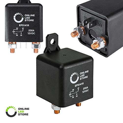
Does this work as a battery isolator?
https://www.amazon.com/gp/product/B00WMBV05Y/ref=oh_aui_detailpage_o02_s00?ie=UTF8&psc=1
What is the advantage of a more expensive device over this simple relay?
I dreamed this up after I had replaced the angle sensor & shift motor, then realized it was an intermittent problem with the ESP module. I installed this last night on a 2001 450 foreman. The relays used can be ordered from Amazon for $9.87 relay kit
It should be possible to fix that loop with defogger repair. I've had good luck with this one, but I'm sure there are others that would do the same. Try to keep the same width of line, especially since its not really carrying any current. The alarm may notice the anomaly in the trace anyway, but its worth a try, to save £435
https://smile.amazon.com/Permatex-09117-Complete-Window-Defogger/dp/B000ALBZJY/ref=sr_1_6?crid=276B1VT8IE9SW&keywords=defroster+repair+kit&qid=1565530105&s=gateway&sprefix=defroster+rep%2Caps%2C138&sr=8-6
Nice work!
Looks like that mount could support a pretty hefty tarheel/screwdriver type antenna. Any reason you chose to to make a hinge mount over using a bracket that bolts to the spare tire carrier? Like this
As long as the circuit is closed, does it matter how it got closed? Meaning, you can use any I/O module to complete the circuit and then hook up a Homekit switch to trigger the I/O module to close the circuit.
For instance, if you used something like this and connect one end to your fireplace (and I'm just using this module as an example as I don't know if it is compatible with your fireplace): https://www.amazon.com/Enclosed-AC-Protection-Bounce-Terminals/dp/B017743I7S/
and the other end to a Homekit switch or outlet. That should work, should it not ?
If you want to skip all of the good, rational advice, I'm here to offer you a way to get him out of your life as quickly as possible.
People will lie, do anything to cover this up, he will do anything, defame your character, adults are much better at manipulating people than you will be most likely, and people will be more likely to believe them. With video proof though, their lies become meaningless, no matter what the situation. You need something like this to back up your story depending on your situation. This might not be necessary, but it's here for you you need it.
To be more effective, I would recommend only launching this plan before doing anything else to try to stop the behavior. This could easily escalate into sexual abuse.
Oh, and if you want a hilariously simple solution that would probably stop the problem all together. Install a loud digital ringer on your door from the inside that chimes when you open the door, and turn it on at night. Every time your door is opened it will ring, and scare him away. He also won't be able to turn if off without making it ring.
After considering our discussion on this I can tell you for sure what I would do if I were in your situation. Since you already have a solar system in place and not starting from scratch you will need a DC-DC switching power supply to replace the AC inverter. I still have never seen one for sale that is suitable for mining so I would build my own to run a single ant s9 based on the design I have tested extensively running 2 ant s5. The design to run 2 s5 is pulling about 700 watts so we need to scale that up to do about 1400 watts. To get right to it these are the parts you'll need, I'll explain in a bit how it will need to be put together and how I came to this design in the first place. After I get all that out I will try to answer some of the other questions folks have about a fully stand alone system. For your needs you will only need the DC power supply/switch/regulator.
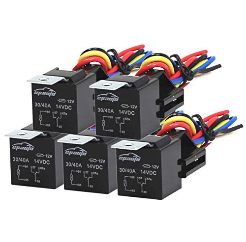
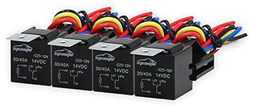
2 of these (note it's a 5 pack so you'll be getting 10 relays total. 8 will be used) about $28
https://www.amazon.com/Pack-EPAuto-Relay-Harness-Bosch/dp/B017VDI0GY/ref=sr_1_1?ie=UTF8&qid=1468169603&sr=8-1-spons&keywords=12v+relay&psc=1
1 of these about $70
https://www.amazon.com/Tracer-Tracer1210RN-Charge-Controller-Regulator/dp/B008KWPGS6/ref=sr_1_5?ie=UTF8&qid=1468170133&sr=8-5&keywords=mppt+charge+controller
10 of these about $200
https://www.amazon.com/Nextrox-Converter-Regulator-Step-Down/dp/B00BWKXTUU/ref=sr_1_11?ie=UTF8&qid=1468169653&sr=8-11&keywords=12v+voltage+regulator
Those three items are an mppt charge controller that will be used to control the relays. The 12v relays which will allow you to safely control the power switching and voltage regulators to make sure the power stays clean so as not to damage your gear.
Here's how it goes together, note that all regulators and relays will be hooked in parallel to allow us to get to the desired total amperage;
-Positive bus lead connects to relay pass in
Once this is connected as such pressing the orange button on the charge controller front panel will activate the relays allowing power to flow to the regulators which will then even it out and pass it to a secondary bus which will then have the miner power cables hooked to it and power the miners.
By using the lamp controller feature of the charge controller you get low voltage protection. If the batteries get low (even though sounds like you won't have much of a problem with that) the lamp controller will power down the relays and therefore stop the miners. It will automatically reconnect when the battery charge comes back up to safe level.
The idea is to have all this in a box with cooling fans (12v dc case fans) and size it to power a single miner. This box of parts gives you about a 15% efficiency boost over using a big inverter. The cost of an inverter to do this is about $2000, my solution costs about $300, thus dramatically reducing total system costs and allowing a modular approach that will scale while limiting down time due to equipment failure.
Thanks! I'm in Los Angeles, only electronic components place I can think of is Fry's Electronics: www.frys.com
Would something like this work? https://www.amazon.com/SMAKN%C2%AE-SRD-12VDC-SL-C-Channel-Level-Module/dp/B00MMW0XWY/ref=pd_sim_60_3?ie=UTF8&psc=1&refRID=VZ0TCJ9326VS28VJSDEJ
Thanks again for your help.
Personally, I would just go for the aux. Save yourself a ton of money, and don't worry about the bluetooth pairing. If you're dead set on bluetooth I apologize for not helping in that field. I don't know much pertaining to it.
Here is the aux kit: http://www.amazon.com/BMW-82-11-149-389/dp/B000PA00XM
I have a gas fireplace that was controlled by a switch on the wall. The switch was a low voltage switch that essentially just connected two wires together to turn on the fireplace and disconnected them to turn off the fireplace. The electronics that control the fireplace are behind a panel underneath the fireplace, and there is a decent amount of room and a power strip in there. I believe most gas fireplaces controlled by a switch on the wall have a similar setup.
So what I did was plugged in a Lutron Lamp smart plug (https://www.amazon.com/Lutron-Wireless-Lighting-PD-3PCL-WH-Assistant/dp/B00KHSXB60/ref=mp_s_a_1_3?keywords=lutron+lamp+dimmer&qid=1564055576&s=gateway&sprefix=lutron+lamp+&sr=8-3) to the power strip below the fireplace, and then I plugged in this AC/DC relay to that (https://www.amazon.com/gp/aw/d/B017743I7S?psc=1&ref=ppx_pop_mob_b_asin_title). What the relay does is just make a connection between its terminals whenever the outlet it’s plugged into (the Lutron Lamp plug in this case) is turned on. I then spliced the wires going to the switch on the wall and connected them to the relay. Then, the last step was to pair a Lutron Pico remote / switch (https://www.amazon.com/gp/aw/d/B00KLAXOE8?psc=1&ref=ppx_pop_mob_b_asin_title) to the Lutron lamp plug, and then I replaced the switch on the wall with the Lutron Pico switch. Now I can turn the fireplace off and on from a switch on the wall still, but I can also control the fireplace from HomeKit, Google Home, Alexa, etc. I also set up some rules to automatically turn off the fireplace if it’s been on for 3 hours, and to notify me if it turns on and I’m not home. These are just in case we accidentally hit the button to turn it on while we’re in bed or away or whatever.
I just put lights on my drive.
I used this on the front and this on the rear.
Since the motorcycle taillight has a circuit for both the tail light and brake light, I wired the tail light to the same switch as the head light. I bought an adjustable motorcycle led flasher and put the brake light on a second circuit and switch.
So, I ended up with a headlight/taillight combo on one switch, and a brighter, flashing taillight on the other switch. Both of these circuits are only active when the key is turned on. I am quite pleased with the outcome.
While I was in the dash, I also added a 12 volt power port for charging phones and my bluetooth speaker, which has a mount on the dash.
FYI, there is a factory power harness which has unused 12 volt power located behind the key switch.
I'll try to post pics when my phone is charged.
Feel free to ask any questions. I'm pretty familiar with the electrical on the drive now (mine is gas).
Edit: Here are some pics. Excuse the dirty cart. Believe it or not, that little cheapo light bar actually put out too much light. At first, it would light up a stop sign 150 yards down my street. I aimed it at the ground to keep from blinding oncoming traffic.
How to tell if you have DSP. You will need the BM53 radio to add auxiliary to have Bluetooth streaming. Buy used on eBay. For non-nav vehicles, the radio is located in the dash (with the amp in the trunk), beneath the little flip-up panel and behind the MID. It's pretty simple to upgrade. BMW sells an auxiliary input retrofit kit for the BM53 radio. Pair that with an aux->Bluetooth device that you can keep in the glovebox.
Most simple relays I've used have 3 connections, allowing 2 choices - either NC or NO. Just wire it for what you need.
I can't help with ordering to CA - but this is one where you can see in the pic that you can wire it either way.
https://www.amazon.com/dp/B00E0NTPP4/ref=cm_sw_r_cp_apa_i_67eACbFK3XZPA
Step 1. If it is the cheapie electric baseboard heat, you most likely have a 120v or 240v thermostat. Find out which.
Step 2. You'll need this for 240 (or if you can find one to mount in a switch box, that would be better): http://www.amazon.com/Aube-RC840T-240-Switching-Electric-Transformer/dp/B0037MXM1C/ref=pd_sim_60_1?ie=UTF8&dpID=31RasVuVDpL&dpSrc=sims&preST=_AC_UL160_SR160%2C160_&refRID=1K9Z0QT4F1AHDX7W166G
Or this for 120v: http://www.amazon.com/Honeywell-RC840T-120-Electromechanical-Relay-Built/dp/B00D5YLY2G/ref=pd_sim_60_4?ie=UTF8&dpID=41c-k5UMUgL&dpSrc=sims&preST=_AC_UL160_SR160%2C160_&refRID=1K9Z0QT4F1AHDX7W166G
Step 3. Use the above relay to hook up an Insteon Thermostat.
I used a reed switch connected to a GPIO port to detect if the door is open. I used Twilio to send me an SMS. I used a relay board (like this one) in parallel with the manual pushbutton to toggle the door. And I used Python to serve the site. Let me know if you have specific questions.
i would use a plain old relay.
something like this and then like you said, heat if too low, fan if too high. i prefer digital temp probes like the ds18b20. It comes in a nice water proof package so you can spill beer (or wine?) on it without worry.
Ok well nice job deleting as much as you can it's very necessary on these bikes. Do you have a manual? I ha e a copy of a minimal wiring diagram I used on mine I can forward to you so you can trace your own wiring. Have you tested the LEDs? Most of these old bikes can't read a signal that small and need a relay (ex:AUDEW 2-Pin Electronic Turn Signal Flasher Relay Fix Motorcycle Turn Signal Hyper Flash https://www.amazon.com/dp/B011BTMDQM/ref=cm_sw_r_cp_apa_KmirzbTJDKYAQ)
With a 6.5 gallon tank it would be sad to only take advantage of 70 miles at a time.... Lol
Get yourself a Voltmeter and test the resistance on the ignition pack, THE STATOR (in case you were unaware... Stator is:the stationary portion of an electric generator. It's under the right side cover. Replacements are not easy to find...trust me...) you're actually at an advantage with no wiring on these bikes. The 80s Japanese bikes were notorious for tons of wiring for no reason.)
I don't know how proficient you are mechanically and I don't want to suggest something crazy and out of you're league... But look at this https://youtu.be/nFAnxpPOlnU
Wish I had a picture of when it was finished but I can't seem to find one... Here was my 80' xs850 http://i.imgur.com/TPY4UMy.jpg
You can look in to these relay modules they are cheap and easy to use. As for your EM interference on you previous project. Did you switch the relay with an output of the Arduino ? Because relay's are using around 50mA when switched while an output can only provide 20mA. The Arduino resets as a result.
Just use a cheap IR light for when you want to watch movies or do stuff in the dark. I will test it once my Quest gets in.
https://www.amazon.com/CMVision-IR30-WideAngle-IR-Illuminator/dp/B001P2E4U4
Thank you :)
I used a simple 5v relay module, very similar to this one here: https://www.amazon.com/dp/B00E0NTPP4
The one I'm using is very old, bought it years ago and I don't remember w here, but the one in the amazon link above is very close. In my video, I show the module starting at around 6:58 - https://youtu.be/1mtX4kB1EEA?t=418
You can also use a transistor for this. Pretty much any logic-level transistor will do, or any transistor that can be turned on with 5v of power. I'm working on another project to control an RGBW LED strip, for that I'm using transistors and the models I'm using are IRL2203 and IRLU024 MOSFETs.
I'd just get a pack off Amazon like this, includes the harnesses too.
IMO, being a professional 12v installer, a simple relay rated for your application is the easiest, safest way to accomplish what you're trying to do.
terminal 86 to ground, 85 to a switched ignition 12v power source, and the two other terminals connect one battery bank to the other.
This is a proven setup up for years on cars with hydraulics or demanding audio systems where multiple batteries are installed in a particular vehicle.
This is the exact one I got:
http://www.amazon.com/Genuine-Subaru-H201SSC100-Interior-Illumination/dp/B0097EJRSQ/ref=sr_1_1?ie=UTF8&qid=1453425460&sr=8-1&keywords=H201SSC100
Keep in mind these will only come on if the cubby light is on (i.e. if the headlights are on). so if you want it to turn on when you open the door, your headlights will have to be on (for me, I have the auto headlights so it will turn on when it is dark enough. I'm not exactly sure if the auto headlights are a limited trim option or standard though)
For the 2016's its a bit harder to get to the plug to plug in the kit. Youll need to take off the driver side knee panel and the glove box entirely. Then there are two bolts that hold the bottom of the front center console (head unit and HVAC controls). There are instructions on some of the forums on how to do this.
This: http://www.amazon.com/BMW-82-11-149-389/dp/B000PA00XM
Hook your iphone/ipod into the aux input.
You might need these: http://www.amazon.com/Leegoal-Panel-Dashboard-Dismantle-Installer/dp/B00D7XNQHG/ref=sr_1_3?s=automotive&ie=UTF8&qid=1452048112&sr=1-3&keywords=panel+removal+tool
And watch this for how to install it: https://www.youtube.com/watch?v=0qmXdnFdjwk
I found this job to be pretty easy. I installed in the back of pocket below the radio. I can tuck the wire away that way.
Everyone is right about the maintenance. Stay on top of it or it will get out of control.
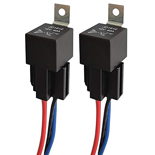
ARTGEAR JD1912 Car Relay Harness 12V 40A 4 Pin SPST Harness Sockets with Color-Labeled Wires for Automotive Truck Van Motorcycle Boat (Pack of 2) https://www.amazon.com/dp/B078T8CMF6/ref=cm_sw_r_cp_apa_i_s7EQCbJ57W1HB
It was really easy since there is a 110 outlet under my fireplace. I used the relay below to trigger the switch and a TP-link smart plug. It was simple to hook up.
https://www.amazon.com/gp/product/B017743I7S/ref=oh_aui_detailpage_o01_s00?ie=UTF8&psc=1
clinometer
Removed the radio and capped it with abs plastic, fit it with a usb charger and [four of these switches in different colors] (https://www.amazon.com/gp/product/B001GH1PU0/ref=oh_aui_search_detailpage?ie=UTF8&psc=1) using these housings
the switches got to [relays] (https://www.amazon.com/gp/product/B017VDI0GY/ref=oh_aui_search_detailpage?ie=UTF8&psc=1) that are powered [by this fuse box] (https://www.amazon.com/gp/product/B00QMTAZ1W/ref=oh_aui_search_detailpage?ie=UTF8&psc=1) that is mounted to the top of the OEM fuse box under the hood.
Those power my OBHS and OBA. Other two switches not in use yet, hoping for rock lights/light bar some day maybe?
Removed the old fog light switch panel, replaced with abs plastic and volume control that goes to an amp that goes to a stereo jack that i just plug into my phone for music.
OK, here's an approach that should work and has worked for others:
Use a TP-Link HS100 Smart WiFi/Alexa-enabled plug driving an isolated relay, e.g.. https://amazon.com/Enclosed-AC-Protection-Bounce-Terminals/dp/B017743I7S/ref=sr_1_2?ie=UTF8&qid=1483241234&sr=8-2&keywords=120v+Relay+switch
Here is a quote from a reviewer who controlled a fireplace:
>Does exactly what it's supposed to. I used this with a TP-Link Smart Plug to allow me to use my Amazon Echo turn my gas fireplace on and off. The project took literally 5 minutes to hook up and works great. If I were going to pick any nit, I wish they had a version with a solid state relay so it doesn't "click" on and off, but that's really minor, and for this price, it can't be beat.Does exactly what it's supposed to. I used this with a TP-Link Smart Plug to allow me to use my Amazon Echo turn my gas fireplace on and off. The project took literally 5 minutes to hook up and works great. If I were going to pick any nit, I wish they had a version with a solid state relay so it doesn't "click" on and off, but that's really minor, and for this price, it can't be beat.
Setup the smart plug at an AC outlet close to the FP. Then plug the AC cord that comes with the relay module into the smart plug. The two wires that control the FP connect to the Gnd and NO contacts of the relay. Those two wires are very low voltage and current ("Millivolt circuit") that turn on the fire when connected. They should never contact a 120V circuit, which is why you need the isolated relay module.
You can get a relay like this and then connect the fan to the normally closed contacts on the relay, and the intermatic timer to the coil. And if you live somewhere with 220v then make sure to get a 220v coil version.
If you are up to doing a bit of wiring you can put together a rig that will work.
To do so you need to get a powered relay. There may be some on Amazon. https://www.amazon.com/Enclosed-AC-Protection-Bounce-Terminals/dp/B017743I7S/ Maybe something similar to this one but maybe one that already has a 220 plug on it.
Then use a iDevices or iHome plug to power it.
If not sure about wiring get an electrician to handle it.
Not quite a standard way of doing it but it would work.
Yes,
Two issues.
1.you need a digital flasher. I use these. AUDEW 2-Pin Electronic Turn Signal Flasher Relay Fix Motorcycle Turn Signal Hyper Flash https://www.amazon.com/dp/B011BTMDQM/ref=cm_sw_r_cp_tai_i_O4o4AbK3MZFNH
2.most Japanese MC’c back feed the dash indicator ( TS) from the signals themselves. The guaranteed and easy fix ( without all the resistors and janky wiring is to use one of these. Kuryakyn 4709 Diode Kit https://www.amazon.com/dp/B000TK7XMY/ref=cm_sw_r_cp_tai_i_s7o4AbN8C7F71
Then get into your headlight bucket or under the dash. Find the turn signal wires and the indicator socket. Pull out the indicator bulb holder and cut the two wires going to it. Wire up the Diode. 1 red wire connects to each right and left positive wires. The blue wire goes to the center conductor ( wire you cut ) of the indicator bulb. The black wire connects to the other wire of the indicator bulb. The black wire goes to ground - any ground wire. The left over wire ( you cut ) from the original Indicator wire just gets taped / shrink wrapped over as it is no longer used.
This will fix everyone’s “LED lights don’t work, don’t flash, stay on” problems as long as the original lights worked. This is your fix. If you ever change back to stock. It still works with no changes. This works on every Japanese bike that doesn’t work correctly with LEDS. Some bikes you can get away with changing the indicator bulb for an LED as an led bulb is a diode, but this solution only works if they didn’t backfeed the Indicator light across the negative terminal ( outer side ) of the bulb.
I’m using a Rugged Ridge antenna mount and a 2ft Firestik antenna on a medium spring. I would prefer 3ft, but I had the 2ft from my last vehicle and wanted to reuse. Like the setup on that.
I have a medium-ish sized CB radio, which is just too big to go anywhere in the cab. I would recommend going with the Cobra 75 radio that a lot of Jeepers use. Not easily stolen, doesn’t take up room.
Use something like Honeywell's Aube RC840T-120 and you can connect any low-voltage thermostat to control that fan.
If you want to make this work with an actual thermostat, you just need a 120v heating relay. That takes the 120v heat wires, and gives you a 24v thermostat connection for a smart thermostat.
Sort of. There's sort of a progression going on. It's a good idea to ensure you can cut the power between the two manually as a safeguard.
I used this
last time with a fuse on each battery, and just kept the accessories live to the house battery full-time. Turned it on when I wanted to charge or the odd case of boosting my starter battery from the house. Dead-simple hook up, I just had to pay attention to when I should have it on or not. Mostly cut it on before I start the vehicle, watch the dash voltmeter to know when everything's charged, then cut it off before I start using the house without the motor running.
I'm getting this one next time to replace the one above. I'll have the common on the accessories, and be able to run them off of the starter, the house, or both. "both" would also be used to charge the house off the alternator, and I'll have it there almost all the time, with the addition of a VSR (below). It also has an "off", in which nothing is connected to anything. You'd still want to wait until the engine is running to re-charge a dead house battery, and switch it to only "2" to keep from draining the starter battery, unless you install one of the next two items.
This makes a nice addition wired right alongside either switch. Tells you how much juice each battery has.
To keep everything 100% un-screw-up-able, this is going to go between my starter battery positive and my new manual isolator switch in back. If either side gets to charging voltage, it will connect to the other side. That means the alternator will always charge the starter battery, but also charge the house battery AND if I connect a charger to the house battery (like a generator or plugging in to shore; solar that fits on a van would take several days to charge a battery from dead to van-crankable), then it will automatically charge and maintain the starter battery, too. Neither can drain the other past the point it wouldn't crank the van.
Charging relays are much cheaper than a VSR, and are automatic in a more rudimentary way. This will do the job fine for most cases, and is a little less expensive than a VSR. The big lugs on it hook up just like the two on the VSR above, except it's not automatic - you hook the small poles up to stuff to tell it when to connect the big lugs. The small positive goes to the other, smaller wire going into the alternator, only allowing it to connect if the alternator is charging. The small negative can go straight to the large negative, but I'd run it through a small switch in the dashboard somewhere (and the other side of that switch back to the large negative lug) to allow me to disable charging house battery off the alternator. it's a decent blend of manual and automatic control, with a relatively tiny price tag. This pretty much needs to go under the hood, though, whereas the VSR could actually go in the power center or under the hood. Remember that either would go on the 4 gauge between starter battery and rear isolator, if present; it's the longest fat-wire in the whole system. some people skip the manual isolator switch altogether, and just go with a VSR or charging relay.
Only because I happen to have one of the first switches linked here already, I'd install it between the large lugs of the VSR or charging relay, to bypass it manually. If I didn't already have one, I'd just count on using a set of jumper cables to do that in the rare case I should need to turn that switch on.
You can connect it to an AC relay.
I use mine to open and close my garage door.
You want a relay that switches the 110v mains with a 24v signal like this:
https://www.amazon.com/dp/B00D5YLY2G/
Then you can use any of the normal smart thermostats (which switch on 24VAC).
This one (which I use) even provides the C wire (common) which the ecobee needs.
I tinkered with two different methods, both of them use Gordon's WiringPi library to manipulate the GPIO. One of the setups uses a PowerSwitch Tail II to power off the entire machine and the other method used a simple relay to toggle the reset button. My preferred method was the firs method because it FORCED power off no matter how frozen the mobo was.
By the way - the close observer will notice that the PowerSwitch Tail is really just a relay enclosed in a box. I prefer to use it when handling 120V AC so I don't make shiny sparks.
So, the question is, if I bought this kit (https://www.amazon.com/Genuine-Subaru-H201SSC100-Interior-Illumination/dp/B0097EJRSQ) - could i just unplug the blue lights and plug in the red ones?
there are easier solutions but since this is DIY I recently put together a circuit using one of these
https://www.amazon.com/HiLetgo-Version-NodeMCU-Internet-Development/dp/B010O1G1ES/ref=sr_1_1?ie=UTF8&qid=1466965785&sr=8-1&keywords=nodemcu+v3
It's programmed via the arduino IDE and is simple enough with a bit of googling for any programmer to get working. I have it connected to one of these
https://www.amazon.com/SunFounder-Shield-Module-Arduino-Channel/dp/B00E0NTPP4/ref=sr_1_4?ie=UTF8&qid=1466965844&sr=8-4&keywords=arduino+relay
3 wires from the nodemcu to the relay. VCC, ground and one of the datapins. Just make sure you use the 5V pin for VCC as the 3.3V ones didn't work.
Then apply power to the relay and he nodemcu. I used an old 5V cellphone charger that I cut the plug off of and direct wired it to the boards. After that I made a short 6" extension cord and split one of the wires. It goes into the relay. After that it just works.
You will need a way to solder the wires and a breadboard lets you test before doing the final wiring.
Yes, also, you might want to consider adding a relay and fuse block for accessories:
[Relay]( https://www.amazon.com/dp/B078T8CMF6/ref=cm_sw_r_tw_dp_U_x_bqmiDbBMSEFWX via @amazon)
[Fuse Block](https://www.amazon.com/dp/B00QMTAZ1W/ref=cm_sw_r_tw_dp_U_x_yrmiDbE7ZJ4HY via @amazon)
Wiring Guide
The fuse block should be under the seat/tail in a protected area.
Yes! That does make sense. I was looking on Amazon, and came across this relay. with the drawings, should be similar. Off with a positive trigger.
https://www.amazon.com/ONLINE-LED-STORE-Pack-Interlocking/dp/B01KVZ2MU4?ref_=fsclp_pl_dp_2
If it requires line voltage control, it can be adapted using a relay- transformer like this one: Aube Technologies RC840T-120 Electromechanical Relay with Built In Relay https://www.amazon.com/dp/B00D5YLY2G/ref=cm_sw_r_cp_api_i_WLZ3AbDVCCM0W
Maybe I'm not quite following, but wouldn't you use something like this bulb:
https://www.amazon.com/BYB-Ceramic-Infrared-Emitter-Brooder/dp/B00HFNZ59Q
plugged into this to secure it:
https://www.amazon.com/Simple-Deluxe-Listed-Aluminum-Reflector/dp/B01E9IY6US
with one of the wires cut and running through this to switch it on and off:
https://www.amazon.com/gp/product/B00E0NTPP4
You are going to need to do a bit of research. You will need two additional things: something to read the temperature (one-wire type ones like DS18B20 are easy to use: https://www.amazon.com/SunFounder-DS18B20-Temperature-Arduino-Raspberry/dp/B013GB27HS/ref=sr_1_7 ) and a relay to turn on the heat lamp: https://www.amazon.com/MCIGICM-Channel-Raspberry-Optocoupler-Expansion/dp/B072BY3KJF/
The rest you can find on the internet, how to read the temperature, how to operate the relay, and then put them together.
Instead of a resistor you can replace the blinker module with an adjustable $4 one from amazon:
https://www.amazon.com/AUDEW-Electronic-Signal-Flasher-Motorcycle/dp/B011BTMDQM/ref=sr_1_1?ie=UTF8&qid=1494862870&sr=8-1&keywords=Blinker+relay
http://www.bareconductive.com/
or
http://spectrum.ieee.org/geek-life/hands-on/how-to-brew-your-own-conductive-ink
You also look at the kits to fix rear defrosters on cars.
http://www.amazon.com/Permatex-09117-Complete-Window-Defogger/dp/B000ALBZJY
1.
Which wires specifically? In general, I was planning on going for heat-shrink solder terminal connectors and crimp connectors.
One of the reasons I posted this is because there are quite a few connectors and I am still not entirely 100% sure what I need. Obviously when screwing something in to a screw terminal block, the ring crimp connectors. But when joining wires, I would prefer to use the heat-shrink-solder type, but there are also butts and blades (heh).
I bought this set of terminals, figured I'd need them anyways: Assorted crimp terminals
I am probably going to buy this set of solder terminals: Fancy solder terminals
I am pretty good at soldering (though usually circuit boards, not automotive wires, hence not entirely knowing what to do.) I have easy access to a heat gun as well.
2.
Well, both - the breaker goes on the battery, and it sets the maximum amperage for the entire new fuse block and everything attached to it. The fuses go for each individual circuit. I want to use just one fuse for each circuit, instead of having several different circuits sitting on the same fuse, largely for my own desire for neatness and debug-ability. I could have one main fuse instead of the main breaker, but I figure that they will serve the same function and I may as well go for the re-usable option.
I was going to go for this breaker: Fat breaker
That said, I bought this fuse kit, which includes up to a 35A fuse, which will be more than enough. I also bought this fuse holder, in case I decide to use one main fuse instead of one main breaker. (I figured I'd need both of these anyways for some project, may as well get them even if I don't use them right now.)
Fuse Kit
In-line Fuse Holder
---
In general, I think my system will basically look like this:
Battery 12V + Breaker = safe 12V
Save 12V + ignition 12V (do I need a fuse here?) + Relay = ignition-switched 12V
Ignition-hot 12V + Fuse Block + ATC/ATO Fuses = eight fused circuits
Fused circuits, obviously, feeding from above. I will probably add a 20A switch in line with high-power circuits, just in case, as an emergency switch.
Fused circuits will terminate at something like this Ground Bar.
 
What do you think of this proposed setup?
I do realize that it's kind of overkill for what I want.
But you can probably agree that overkill is better than your car burning down!
First this going to be removed as what to buy questions go in the meagthread sticked at the top of the feed. As for the fireplace, I don't recommend it when you're dealing with something that could set you house on fire. People do put switches on fire places here though. You can use any switch for the fan as all HomeKit switches support timers. Make a scene that turns the fan on. Set an automation for when the fan turns on turn on the scene. Make sure that the timer setting at the bottom is set to how long you want it on.
​
Edit: Found this on a forum.
>I was able to get this to work, though with a much different setup than I was initially envisioning.
>
>The fireplace I was working used a low-voltage switch on the wall with a 2-wire cable between that and the fireplace guts (below the firebox). It also has 2 outlets in that same area: one labeled REMOTE and one labeled FAN. As far as I know, both outlets are always on and the labels are just for fun.
>
>Here is what I did:
- Caseta plug-in lamp dimmer plugged into one of the outlets
- Set this dimmer to switch mode (no dimming) - see Caseta Advanced Installation Guide for details
- Plugged a 5V DC power adapter I had laying around into the dimmer
- Connected the output of the DC adapter to the input of a relay. I used the Sunfounder 2-channel 5V relay module
- Cut the cable that went to the wall switch and connected it to the output of the relay instead of the switch
>
>This solution does completely disable the wall switch but - in my case - it was in a crappy location anyway.
>
>Some other notes on this:
>
>- I got a 2-channel relay module since it was cheap and readily available but only one channel was needed
- I was a bit worried about the heat in the area with the electronics but I measured the temperature of the dimmer with one of those point-and-read thermometers after the fireplace was on for a while and it came up at 105. The specs for the Caseta say the operating temp tops at 104 but it's been running for over a month now and - so far so good.
​
Is there any reason why you wouldn't just buy a normal 12v relay and run it to the ignition switch from the fuse panel instead of spending $60 on one with a relay built in? For example use these:
https://www.amazon.com/OLS-6-Way-Blade-Indicator-Protection/dp/B00QMTAZ1W/ref=sr_1_3?ie=UTF8&qid=1497658098&sr=8-3&keywords=fuse+panel
https://www.amazon.com/OLS-Split-Charge-Relay-Switch/dp/B01MYPTVJD/ref=sr_1_1?ie=UTF8&qid=1497658136&sr=8-1-spons&keywords=12v+relay&psc=1
If you already have a IR camera, you probably just need more light.
Something like this, there are many more choices.
https://www.amazon.com/CMVision-IR30-WideAngle-IR-Illuminator/dp/B001P2E4U4
5 Pack - EPAuto 30/40 AMP Relay Harness Spdt 12V Bosch Style https://www.amazon.com/dp/B017VDI0GY/ref=cm_sw_r_cp_api_J6h7BbAHCG8Q8
Pins 85 & 86 go between your transformer and doorbell (doesn't matter which way it's wired). The sensor goes to pins 87 and 30.
Edit to add: any Bosch style relay like that will work. I bought the 5 pack because I was going to use them for my alarm system to convert normally-open flood sensors to normally-closed (which is the only kind of sensor my alarm system can read) but the switching voltage was too high (but ended up being perfect for the doorbell)
Got a handful here and there but mostly aesthetic mods. I've got:
Bully Fuel Controller by GMan
Kuryakyn Hypercharger
Integrated Tail Light
Electronic Flasher
[Switchback Turn Signals] (https://www.amazon.com/dp/B076GLLS3T?ref=ppx_pop_mob_ap_share)
I have a few more on my list to-do but I broke my hand so I'm off the bike for another 3 weeks ),:
Often base stations are cameras that track an IR constellation on the HMD.
I mean use an IR lamp to illuminate your room for the inside-out tracking cameras, which do tracking off edge detection of objects in your room.
If you live in an area where they salt the roads look into sealed relays. I’ve had quite a few fail over the years from rust even when tucked up under the hood. And I agree with the other guy make sure the wiring can handle the current draw but also the relays.
I picked these up for my fog and driving lights.
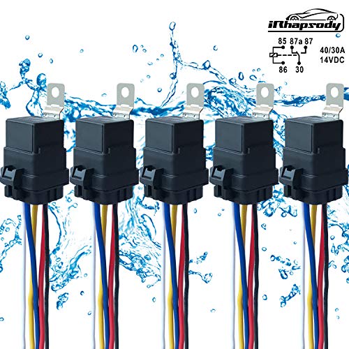
5 PACK 40/30 AMP Waterproof Relay and Harness - Heavy Duty 12 AWG Wiring Harness - 12V DC 5-PIN SPDT Bosch Style Automotive Relay - MAX 14V DC
https://www.amazon.com/dp/B074FSZWVT/ref=cm_sw_r_cp_api_r5RTBbEPD9G2K
Here are my lights.
https://m.imgur.com/nkpEsKQ
https://www.amazon.com/dp/B017743I7S/
This opens/closes a relay that you can wire into a contact sensor of some sort. Plug it into the clapper and you can do whatever automation you want with it. Normally use these on control4 systems, so not sure what zwave/zigbee/usb contact sensors are out there.
If Fibaro's smart implant was available this is the perfect use case.
https://www.fibaro.com/us/products/smart-implant/
Since it's not available you can still use the Fibaro RGBW module over ZWave in Input/Output mode and control the DC circuit of the speaker.
☝️This is how I would implement it.
Another solution is use any ZWave/zigbee relay module and use a AC-DC Relay.
(https://www.amazon.com/Uxcell-a14051000ux0379-JQX-13F-Power-Relay/dp/B00NWHJ5N6/ref=pd_aw_sim_263_3?_encoding=UTF8&pd_rd_i=B00NWHJ5N6&pd_rd_r=beb5c684-2d9d-11e9-9da1-2f38c3bf93b4&pd_rd_w=HxKEf&pd_rd_wg=VItgd&pf_rd_p=469620d9-3e90-496d-9dc8-b19f900ba5fe&pf_rd_r=2TB1210HZWRKN4Z6NFBF&psc=1&refRID=2TB1210HZWRKN4Z6NFBF).
What makes Nold interesting is the ability to control 2 doors as well as attach a magnetic sensor to let you know the open/close state. This is why I loved the WeMo Maker so much.
If you want an inexpensive garage door opener, use this with a WiFi outlet:
Enclosed AC/DC Power Relay with Protection & De-Bounce. Screw Terminals. 120V Trigge... https://www.amazon.com/dp/B017743I7S/ref=cm_sw_r_sms_c_api_Zi7KBb1KYGJB2
Those wires are going to be battery, flasher out, and ground. For standard filament bulbs, just buy a 2 prong standard mechanical relay and leave the ground disconnected. If you upgrade to LED bulbs, switching to a load independent relay (usually 3 prongs) will fix the fast blink issue.
In the 3 prong the coil side seeks ground for discharge through the additional ground, otherwise it has to discharge through the circuit. Because the load (resistance) is low with LED bulbs, the capacitor that controls the coil latch timing can discharge really fast and the flasher blinks fast or not at all. There are some electronic relays without a standard coil/cap that have a rheostat in them that allows you to adjust the discharge load. Those will be 2 prong - they discharge through the bulbs/circuit. The standard mechanical relays are available at any auto parts store.
Electronic solid state 2 prong with adjustable load:
https://www.amazon.com/AUDEW-Electronic-Signal-Flasher-Motorcycle/dp/B011BTMDQM/ref=sr_1_4?ie=UTF8&qid=1493815500&sr=8-4&keywords=electronic+flasher
Standard mechanical coil 2 prong:
https://www.amazon.com/Bussmann-NO-552-12-8-Thermal-Flasher/dp/B000GKAZCW/ref=sr_1_1?ie=UTF8&qid=1493815609&sr=8-1&keywords=12v+flasher
3 prong with load independent grounded coil (my preferred type - these still need some load to function):
https://www.amazon.com/uxcell-Vehicle-Blinker-Flasher-0-02-20A/dp/B00BLZ9XQK/ref=pd_sbs_263_2?_encoding=UTF8&pd_rd_i=B00BLZ9XQK&pd_rd_r=B9EGDRDCQ81ZH9VWKT7A&pd_rd_w=SRsBN&pd_rd_wg=UBlTA&psc=1&refRID=B9EGDRDCQ81ZH9VWKT7A
I really wouldn't worry about relays failing. You aren't talking about tons of cycles or fast cycles, high amperage, or whatever. Using a SSR would be fine for sure, I made a PID to control a freezer ~10-15A draw using a 40A SSR that has run day and night for years without failure.
Here's one from amazon that I have used.
https://www.amazon.com/SunFounder-Channel-Optocoupler-Expansion-Raspberry/dp/B00E0NTPP4/ref=sr_1_5?ie=UTF8&qid=1494422744&sr=8-5&keywords=arduino+relay
The voltage is right, but we are worried about the current. The gpio pin is designed as a signal, which means very fast switching at nearly no current. The relay however does real work and needs current to do it. The transistor will act as the switch that turns the current on at the response of a signal voltage.
You can buy a relay package made for Arduino and Pi that have the transistor and flyback diode preattached, as well as some other protection and a led. I recommend you do that instead of making it yourself.
Edit: For example: https://www.amazon.com/MCIGICM-Channel-Raspberry-Optocoupler-Expansion/dp/B072BY3KJF This one also includes an optocoupler which is a very common and highly recommended safety feature to prevent any voltage spikes on the mains from getting in to the RPi.
Sample relay or mosfet
I did the same thing. Your favorite alexa-enabled wifi plug and one of these should do the trick.
Take a look at your radio model number and compare it to the model numbers in this thread about aux-enabled radios. If you have one that is aux compatible, getting [an aux adapter] (https://www.amazon.com/BMW-82-11-149-389/dp/B000PA00XM) and routing it to the front isn't too difficult - just pull out radio trim piece, radio, AC unit, sunglasses tray.
I ended up drilling a hole in the bottom of the center console panel (empty space next to the passenger heated seat button) and pulling the aux port there, since I found that was much easier to reach than the glovebox.
If your radio is not aux-compatible (they all have the port, just some don't have aux mode enabled), you could always go for the GROM or similar units (the £150 fancy adaptor that they were talking about), use an emulator, or you could splice into the CD player lines.
So, here it goes, feel free to PM if I leave anything unclear.
Sorry if I was unclear....you need to have the Pi first and then building an outlet or switch is pretty cheap. The Pi and other stuff (case, sd card, powersupply) will total out to about $50 but is completely worth it because of all the other stuff you can do with them (media server, web server, whole home ad blocking, game emulation, etc)
Ill start with how to get the pi to control things and then explain how to get the echo to control the pi...
If you only want to control led strip lighting IIRC a lot of them have IR remotes and the simplest solution is probably to build an IR blaster (you will need a couple basic electronic components but cost is less than $10 even if you buy from a radioshack), and then use LIRC (http://www.lirc.org/) to emulate the remote with the Pi. The added bonus is you can then control any other IR remote device (you tv, stereo etc).
If you don't go the IR route you will use a relay to act as a switch. I have used a number of these guys for various projects: relay The basics of a relay is a small voltage opens and closes a magnetic switch that is controlling a much larger voltage. So the 3.3 volts a "general purpose input/output" (GPIO) pin a raspberry pi generates can open or close the other side of the relay that can handle household voltage. I should add the caution..."don't mess with household voltage unless you really know what you are doing you can burn down your house and kill yourself". Anyway the idea is you build a box (think electrical gang box from a home improvement store) where the power comes into the relay and then leaves onto an outlet that you want to control. I have built a couple that are the relay and outlet all in one retrofit outlet box all mounted into the wall (the relay is hidden behind the outlet it is controlling. Then you run some small gague wire (telephone 4 conductor wire works well) from the relay to the pi. The end result is the pi sends voltage on one line to the relay, the relay closes connecting the household voltage to the outlet and whatever is connected to the relay turns on. I usually include a inline 10amp fuze as well because the relays are only rated to 10A and all my breakers are 15A.
Anyway, now you have a raspberry pi that can turn an outlet on and off to tie to the echo you use a piece of software called HA-Bridge . It allows you pi to emulate a smart home device Alexa will recognize. Alexa sends on/off command to the emulated device and the pi can trigger a script to carry out your desired intent.
Right now I can walk into my basement and say "Echo, turn on the basement" Where basement is a group (grouped int he Alexa app) of several devices all emulated by the pi and the pi turns on the Tv and receiver with ir commands from LIRC, the lamps controlled by a relay turning on and off the power to a couple outlets and the Christmas Tree that is plugged into a single relay controlled outlet.
Hope this helps, it sounds like a ton of stuff but is very doable.
You can use one of these with a cheap thermostat.
I personally have a relay tied into my smart house to control my basement baseboard heat.
This should work for your relays: http://www.amazon.com/SunFounder-Channel-Shield-Arduino-Raspberry/dp/B00E0NTPP4/ref=sr_1_4?ie=UTF8&qid=1449242914&sr=8-4&keywords=arduino+relay+board
It's "meant" for an Arduino, but should work with the Pi with a bit of work. It triggers on a 5v input from the Arduino, so you'd need to get the 3.3v line from the Pi's GPIO up to 5v to make it work.
You'll want to figure out the pinout of that plug with a voltmeter. I'm guessing that one of those is common and the other two are for separate banks of LEDs. To control these, you'd run the common straight through and interrupt the two banks with the relays.
As far as Pi vs Arduino, you'll have to do some tinkering either way. Neither have a RTC (real time clock) built in, so you'll either need an RTC shield or connect the Pi to a network connection so it can get the time via NTP. The Pi's main disadvantage is the 3.3v GPIO, while the Arduino's output is natively 5v.
Personally I'd use the Arduino and a cheap RTC: http://www.amazon.com/Donop-DS3231-AT24C32-precision-Arduino/dp/B00HCB7VYS/ref=sr_1_2?ie=UTF8&qid=1449243489&sr=8-2&keywords=arduino+rtc
I use a Koogeek switch with this relay plugged in:
Enclosed AC/DC Power Relay with Protection & De-Bounce. Screw Terminals. 120V Trigger Input. https://www.amazon.com/dp/B017743I7S/ref=cm_sw_r_cp_api_xVgRzbR56SQAV
The relay senses the 120v and closes the circuit of the two wires from your fireplace. In my case the fireplace had an external thermostat connected to it. I took out the two wires from the thermostat switch and connected those two wires to the relay. Now when the relay senses current it closes the circuit of the fireplace switch but without adding any electricity to it.
I'm still in the middle of adding a filament sensor to my OctoPrint setup so I may be missing something, but I think you should be able to use that plugin to achieve pausing a print when the power disappears. The 'Filament Sensor Reloaded' plugin just looks at a GPIO line that you select to determine if filament is present or missing and you can pause the print. If you connect the GPIO to a voltage from the same source as the printer, then you can detect the power removed from the printer and pause. A simple way to do that would be a USB power adapter with a voltage divider from 5V to 3.3V or you could use this power detector - https://www.amazon.com/Enclosed-AC-Protection-Bounce-Terminals/dp/B017743I7S/ref=sr_1_6?ie=UTF8&qid=1506368549&sr=8-6&keywords=iot+relay#Ask
For $9, I'd probably buy the power detector.
Like I said, I haven't experimented with OctoPrint pausing yet, but I would expect the same behavior as pressing the pause button.
It's good but not great. My riding buddy says daylight visibility is ok, but to my eyes it seems a bit dim. That being said I've had several cops behind me and no issues to date.
Functionally it's been perfect except for having to redrill the plate mounting holes. As I'm sure you know it requires an LED compatible blinker relay. Another $7 Amazon purchase. Adjustable Blinker Relay
Future... I'll replace it with something brighter and more integrated. I've toyed with the thought of embedding it into a custom seat pan but it still won't be as bright as I'd like.
Would this work?
Thanks, you're right actually. Since my question is safety related, it's more than reasonable to be precise.
I meant this one
I got this kit: https://www.amazon.com/gp/product/B0097EJRSQ/ref=oh_aui_search_detailpage?ie=UTF8&psc=1
I've used a number of these in my Tahoe, but I've never done something like this. So to be clear the switch that you have has 3 positions? on-off-on? 2 separate 'on' positions? If that is the case I think you could do this by just adding a 'bosch style' relay off of Amazon by running one wire out of your switch directly to the light bar, and from the other side of the switch running to the relay's trigger (86). The dome light will be ran to the relay's source (30). Your light bar would also have another wire running out of relay output (87). Everything would then ground to the frame (or a neutral) from the light bar and from the relay (85). Relay output (87a) would be capped off. The appropriate fuses would be needed before the switch and maybe even between the relay and the light bar. I believe this should work.
https://www.amazon.com/gp/product/B074FSZWVT/ref=ppx_yo_dt_b_search_asin_title?ie=UTF8&psc=1
Yes, all amazon for the CB parts.
http://www.amazon.com/gp/product/B00603DSGO/ref=oh_aui_detailpage_o08_s00?ie=UTF8&psc=1
I got the Cooltech mount for the Cobra 75WXST which is very cool.
http://www.cooltechllc.com/wrangler-parts-accessories/52-versamount.html
This guy on youtube had a good walkthrough on the install. But now I'm probably going to wire it up to my SPOD since I added that a while back.
https://www.youtube.com/watch?v=oajh4Cd3_oY
I used this
Just use a basic Caseta on/off light switch to activate the relay. From the load side of switch just wire the neutral and hot to the relay and connect the millivolt wires to terminals that open/close as the relay functions.
That Caseta switch is used/classified as a plug in the Harmony app.
I have an activity called "Fireplace" that kicks it on. Set up that activity so that it doesn't mess with other activities that are running.
Just wish I had the ability to set a timer in Harmony to shut off the fireplace after X amount of time. Apparently you can't do that with light switches.
If your UPS can provide the signal (most can), you should definitely go for that.
Otherwise, I've used this successfully in the past: https://www.amazon.com/gp/product/B017743I7S/ref=ppx_yo_dt_b_asin_title_o06_s00?ie=UTF8&psc=1
Super easy, plug and play into the GPIO.
Yea of course! Relays are usually used to handle large voltage and current so 12v 2 amps is nothing. Something like this would be perfect
https://www.amazon.com/gp/aw/d/B072BY3KJF#Ask
There are some tricks to using the rapaberry pi with the relay but its pretty simple
These are pretty cheap and get the job done.
Well IMO you should use relays, since they pull a pretty damn decent amount of amps when they first fire up - so get familiar with them if you aren't already, and google bosch style relay wiring. It's pretty damn simple. You just wire to them, to a fused line to the battery, and then inside to a switch and switched power off ur fuse panel.
https://www.amazon.com/gp/product/B017VDI0GY/ref=oh_aui_search_detailpage?ie=UTF8&psc=1
I made it all into a harness with both fans cuz I build deutsch harnesses all day, but really the wiring is pretty rudimentary.
I had to grind down the fan studs and chop up the efan shroud CONSIDERABLY (who knows what it's out of, snagged it off the ground at a jy). I found out later I had another stock xj fan sitting around, but I'm pretty sure even those would have slight clearance issues and would need a bit of a hack job, but it ain't hard at all.
What I can say for sure is that the stock clutch fan must be a MAJOR drag on the engine. When you see how much force it takes to spin one, you'll be shocked. My c1500's clutch fan setup is probably 1/2 the drag, if that.
I am not sure if you are asking how to do this as well as if it's ok to do it but Check out this relay.
https://www.amazon.com/gp/product/B00E0NTPP4/ref=oh_aui_detailpage_o03_s00?ie=UTF8&psc=1
I use it to trigger my Garage door from a Pi. It also works with an Arduino.
Just as an update and thanks for all the feedback.
I bought this: https://www.amazon.ca/gp/product/B017743I7S/ref=ppx_yo_dt_b_asin_image_o01_s00?ie=UTF8&psc=1
Hooked up the fireplace switch cables to the ON and the COMMON wire. Plugged it into the smart outlet and then to the wall. Works perfectly and it all fits under the fireplace with the rest of the controls.
Buy a WeMo then power a relay like this to convert the Ac WeMo to a DC switch. I use this combo with smarthings to open my garage door.
https://www.amazon.com/gp/aw/d/B017743I7S/ref=mp_s_a_1_1?ie=UTF8&qid=1481691193&sr=8-1&pi=AC_SX236_SY340_FMwebp_QL65&keywords=Enclosed+AC%2FDC+Power+Relay+with+Protection+%26+De-Bounce.+Screw+Terminals.+120V+Trigger+Input.
That relay is a nice looking device, good find. They also make a cheaper version, http://www.amazon.com/gp/aw/d/B017743I7S/ref=pd_aw_sim_23_of_6?ie=UTF8&dpID=51RYb%2Ba%2BayL&dpSrc=sims&preST=_SL500_SR100%2C64_&refRID=0HWM3SV21K3EEQT2B97X
Thats spot on. I figured i was pretty lucky in that regard. Good on BMW to allow that to happen though. Here is the cable that i am using right now in my car. Not too pricy, and the install wasnt much of a hassle either.
I'm using one of THESE along with a MonoPrice garage door Z-Wave tilt sensor, and an old Z wave outlet I had laying around. Together, I built a template cover device out of it. The tilt sensor is the feedback and the open/close commands are scripts. Each open/close script basically turns on the Z wave switch (and therefore powers the relay), then turns it off after 3 seconds. I added conditions inside each script as well. For open, it ensures someone is home and the alarm is not on, otherwise it won't work. There is also a 30 second delay, then a condition that the door is actually open or close and a notification if the proper position is not met.
I can try to post the config later on if you want it. Don't have access to it right now.
Thanks!
Did some quick research and found some relays that appear to be pretty straight forward.
I already bought and have these however: https://www.amazon.com/Pack-EPAuto-Relay-Harness-Bosch/dp/B072QXDZRD/ref=sr_1_4?ie=UTF8&qid=1550813873&sr=8-4&keywords=12v+bosch+style+relay
​
Is it possible to make it work with these? Would it be as simple as having my "orange circuit" on the 30 and 87 pin and push the 12v to the 86 and ground to the 85?
​
If not, would this work?
https://www.amazon.com/Support-Relay-Spst-4pin-Socket/dp/B00RVCFNCK/ref=sr_1_10_sspa?ie=UTF8&qid=1550819958&sr=8-10-spons&keywords=SPST-NC+12v&psc=1
​
edit: I put a 10k resistor on the circuit so I could test the open and close when 12v was introduced. I used the example explained above, under the first produt link, as my circuit. When there is 12v power applied, the circuit is closed and it reads 10k. I need to reverse that, where the circuit is always closed without power and only opened when power is introduced to the relay. Do I have the wrong relay?
​
Thank you so much!