Best connectors according to redditors
We found 27 Reddit comments discussing the best connectors. We ranked the 17 resulting products by number of redditors who mentioned them. Here are the top 20.
We found 27 Reddit comments discussing the best connectors. We ranked the 17 resulting products by number of redditors who mentioned them. Here are the top 20.


This appears to be the same cabinet. It just has a crappy description from Amazon.
90lbs total, so maybe 70lbs without the back.
jumper cap.
Think it's called a jumper shunt
http://www.amazon.com/uxcell®-2-54mm-Standard-Circuit-Shunts/dp/B00HR8DGZO
A missing CMOS jumper cap or CMOS jumper usually results in the PC losing settings at every reboot if it's a 2 pin setup, or sometimes various different issues with 3 pin setups depending on the MoBo.
You can purchase spare CMOS jumpers cheaply from Amazon, that'll probably fix it.
https://www.amazon.com/dp/B00HR8DGZO/ref=cm_sw_r_cp_apa_i_Lia4AbD50RWPW
It's cheaper than a repair.
Here is a chart to help you identify the different connectors.
https://www.readymaderc.com/store/images/sma-chart.jpg
The attitude v3s have a sma female connector. you would screw an antenna with an sma male connector to it.
It looks like the amazon listing has it mislabeled or the wrong picture.
This should be exactly what you want: https://www.amazon.com/dp/B006Z95LVI/ref=cm_sw_r_cp_dp_T2_JmSBzb9CSDMKF
Some people have PMed asking for more info, so I may as well put it here.
I used the following:
Monoprice
8inch 28AWG High Speed Male to Female HDMI® Port Saver - Black
For the hdmi port. I also bought another hdmi piece, like a corner basically, it's in some of the early pics, but I didn't use it in the final build.
Tiesto USB Hub 2.0 4-port/4 port hub USB 2.0 Speed Cute Octopus Design - BLACK
I removed the black case on this as well as the black rubber around the usb ports. Then basically hot glued the ports in place against painters tape to make it even and smooth.
Your Cable Store
6 inch USB Micro male to female OTG extension cable
I cut these in half and spliced it into the original Gamecube power switch/button. That way I can leave my pi plugged in and switch it on like a normal console.
Evercool 60x60X10mm 5v Ball Bearing Fan, 3 Pin EC6010M05CA
I set up these fans to run off the main power, so they turn off and on with the pi.
To take apart each Gamecube, i bought this screwdriver.
Also got each person a Buffalo Classic USB Gamepad for PC
And a Retrolink N64 Style Classic Controller For PC
I forgot to mention, I took apart and weighted the buffalo classic usb controllers to be closer to the weight and feel of the original snes controller.
The exact increase in weight is about 10 pennies, but I used 8, 4 on each side, inside the controller, in stacks, glued in, because 8 fit better than 10.
It's a really tiny thing, but if you weight one controller and then hold an unweighted and a weighted one to compare, the unweighted one feels like a toy.
The N64 controller felt decently heavy on it's own. (Plus the rumble pack used to make them super heavy and I wasn't going to try and match that weight.)
Other things, these have in them the pi2 with 1gb of ram. I bought the 2 amp power supplies that are recommended for the pi.
I also bought some other odds and ends: ethernet couplers, each pi has a 16gb sd card in it.
I also replaced the power switch in my final one (the silver one) because I damaged the original switch. I used these switches.
I bought Rust-Oleum metalic base and Dupli-color spray paints.
Tools/materials used:
Bought a dremel, didn't need it.
Used my soldering iron and clamps constantly.
Used a lot of hot glue and gorilla glue.
Mod podge for applying the logos to the top of the cases. I also had some spray sealant from another project I put on the logos, before I applied them to the cases, so the ink wouldn't smear.
I used a fair bit of heat shrink and electrical tape. Also wires with couplers so the entire bottom of the console can unplug from the top if I need to repair something. Basically these though not the same brand.
Much of my job is working with electronics and soldering so this was all fairly easy for me. If you're new to building and soldering, please be careful. I've cut myself and burnt myself quite a few times. Be more careful than me.
I’m not endorsing or recommending this product as I have no experience with it...
https://www.amazon.com/Hubbell-Wiring-Systems-SCSB0-6-Receptacles/dp/B00IS2XD60
A lot of good suggestions here but I also do a fair amount of shows with a lot of RF so I carry 2x ZAPD-1-N+ , and 2 of these 10dB 50 ohm pads and some Ferrite beads, although I've never broken them out.
Something like this would be better. I used one of my mower when something cut through it 🙄
Bulk Hardware BH02621 Flex Connector with 2-Terminal, 5 Amp https://www.amazon.co.uk/dp/B00O7P3JM0/ref=cm_sw_r_cp_api_i_KUoiDb2SV9YZD
18 for the heater wires.
Heater plugs are JST VH series.
https://www.amazon.com/JST-JAPAN-SOLDERLESS-TERMINALS-WIRE-BOARD/dp/B011CPHFLS/
Pins for the above plug
https://www.amazon.com/3-96mm-Connector.../dp/B00X772AXS/
 
All other plugs are JST XH series
https://www.amazon.com/GeeBat-JST-XHP.../dp/B01MCZE2HM/
Look around before purchasing. Those above links are just meant to show the size/type you are looking for.
You can 24 or 26 gauge wire for the thermistor or if using a prewired thermistor just use that.
Look into using silicone jacketed high capacity stranded wire. R/C models often used that type because it is made to be very flexible and heat resistant.
 
Also check that all the wires are crimped properly. Sometimes a connector may only be crimped to barely make contact with the wire and may loosen over time.
https://imgur.com/a/8PnOt
I used one of these, I had them in the drawer. I originally tried to just solder directly to the connector but there wasn't enough surface area to get a really solid connection.
uxcell® 5pcs End Launch PCB Mount Bulkhead SMA Female RF Coaxial Connector Straight https://www.amazon.com/dp/B006Z95LVI/ref=cm_sw_r_cp_awd_qjh2wbR3F8Q5S
I'm currently testing it with my Raspberry Pi receiver and if it performs well I'm planning on making a 3D printed enclosure for the antenna to mount it in/on the car along with a GPS antenna to try and make a mobile receiver.
IDE cable.
http://www.amazon.com/2-54mm-40-Pin-Female-Ribbon-Cable/dp/B00Z5AVRDY
Wow, that's terrible! I'm hoping that mine doesn't have the same DoA problem.
I think that mine isn't working because I lost the stupid CMOS jumper cap. I ordered 100-pack replacement off of Amazon that should be arriving tomorrow. My next step would be to try and return mine to ASUS, but I ended up getting a little "rough" with my mobo when one of the hard-to-reach screws got stripped and refused to come out of the case. I suppose if that doesn't work I'll be forced into buying another damn mobo off of Newegg, since there is the chance that I just damaged the thing out of my own stupidity.
I'll post an update on my solution, so any future googlers who end up stumbling across this conversation know what I did to fix mine as well. Hope you don't mind the extra messages, LegendaryOne.
Also, would you mind posting a link/email address to how you got in contact with ASUS to start the replacement process? It'd be nice to have, in case my future board is DoA.
I've seen them alternatively called JST 2 pin and Molex connectors.
Typically, try looking for them in places that carry RC parts. They tend to have them cheaper than electronics hobby stores.
A quick google search gave me these places (please double check dimensions before buying as /u/ermwhat said)
http://www.amazon.co.uk/dp/B016FD35DE
http://www.componentshop.co.uk/jst-ph-2-pin-silicon-male-lead.html
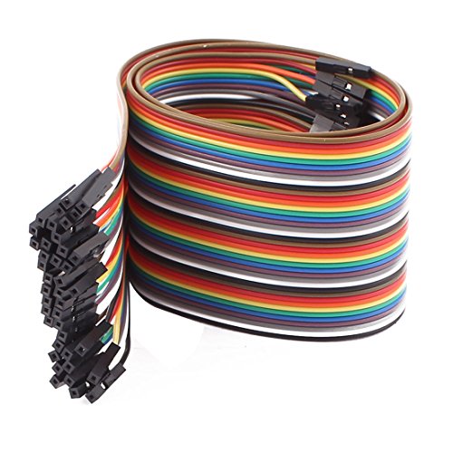
Half a meter should be doable. You'd just need jumper wires between the pins they use instead of mounting it on top. The pins aren't all next to each other so I don't think a ribbon cable would be too easy to pull off.
Something like these, but you may need M/F jumpers.
https://www.amazon.com/dp/B01M1CDI7M
https://www.amazon.com/uxcell-Stereo-Female-Adapter-Connector/dp/B013D1U90S/ref=sr_1_13?s=electronics&ie=UTF8&qid=1518512011&sr=1-13&keywords=3.5mm+female+jack How does this look?
Looks like these. https://www.amazon.com/gp/product/B00MJVKKKI/
One of my 3d printers use them for fan connectors and took me a while to find replacements.
Reddit deleted my last comment, because I use a link shortener, so here I am trying it again.
This is a jumper cap. You could buy one, but it will probably take longer than removing your GPU.
Fadecandy is a USB board about 2 inches long and maybe 1.5 inches wide. Because it's USB, the 3v3 and 5v logic are no longer something you need to be concerned with.
You run a server app on the Pi which interfaces with the fadecandy board and then you just code for the LEDs like normal.
Yes, the Pi is awful at WS2812 LEDs because of the timing. A kernel module was written to let the Pi use the kernel timing clock, but I was less than successful in implementing it, so I just swapped to Fadecandy and never looked back.
Yeah, it's a tad expensive at around $25, but it controls almost 500 LEDs without issue and you can run more than 1 board. I bought a bunch of these to make connecting to the boards simple and changeable. I attach a female connector to all of my WS2812 strings and I can swap them to any fadecandy board in seconds.
The problem using Arduino (which you can work around with some effort) is that you don't get very interactive with the LEDs. I like big programming projects where they can be triggered externally and the Pi is just better suited for the task.
Edit: The only thing I HATE about Fadecandy is that it has no usable mounting points, so if you want to mount it somewhere, you almost have to hot glue it. If they built a Fadecandy board that had the mount holes to match a Pi so I could stack it with the Pi, I'd pay double.
http://www.amazon.com/10Pairs-13cm-2Pins-Female-Connector/dp/B00MJVKKKI?ie=UTF8&psc=1&redirect=true&ref_=oh_aui_detailpage_o08_s00
Not 100% certain that they're the same, but they look like it.
so it looks like if you are plugging the RGB strips into the motherboard, you dont need the power supply for them at all. the socket on the end of the LED strips that the power supply fits into should just directly fit on the RGB header. you could also use an extension, and i think that would make sense. it also looks like you can get splitters although you need male to male connectors to make them work as you want.
Not sure why I couldn't see these replies (I waiters for recommendations) but, I wound up buying these on Amazon and a set of Fat Shark Spro antennas. Honestly I need the soldering experienced anyway lol.
And I found 'em! Sort of...
These are what I remember.. Just bolt 'em to your board and go to town. Now to find 'em in bulk rather than $7/each (WTF?).
Thanks, I'd love to see what you're working on too.
I used copper crimp connectors - not those ones specifically, though. Home Depot has them in the electrical aisle, in different sizes. I got some wire mesh for patching window screens, cut circles a little larger than the end of the crimp connectors, and press fit them into the end of the pipe.
https://www.amazon.com/StarTech-2-54mm-Standard-Computer-Jumper/dp/B00008VF46
Those are what jumpers look like, there's no cable.
They're called jumper caps, they exist in various sizes, but probably you need 2.54mm ones. Ex.