(Part 2) Best switches & relays according to redditors
We found 422 Reddit comments discussing the best switches & relays. We ranked the 240 resulting products by number of redditors who mentioned them. Here are the products ranked 21-40. You can also go back to the previous section.

![6-Gang 12V Rocker Switch Box [60 Amp Max.] [12 AWG Wires][12 Volt DC] SPST On/Off Rocker Toggle Switch Panel Box for Auto Automotive Lights Car Marine Boat Truck Vehicles & More](https://m.media-amazon.com/images/I/51HOQGd94vL.jpg)


![ONLINE LED STORE 6 Pack Bosch Style 5-Pin 12V Relay Kit [Interlocking Harness Socket Holder] [14 AWG Hot Wires] [SPDT] [30/40 Amp] 12 Volt Automotive Relays for Auto Fan Cars](https://m.media-amazon.com/images/I/51vqG7TADXL.jpg)


GOLDEDIT: omg my first gold! Thanks anon!
THE TRIGGER WIRE CAN BE CONNECTED TO Vin + or Vout +
How it looks now: https://i.imgur.com/Xmro9I5.jpg
Parts list (canadian, but you can find everything on amazon and/or ebay, or locally):
Heater Board and Coil: https://www.amazon.ca/BAQI-5V-12V-Voltage-Induction-Heating/dp/B0747NBTBX
MOSFET Relay (for operating the momentary switch): https://www.amazon.ca/DROK-Transistor-Driving-Electronic-Controller/dp/B01J78FX9S (if you want to do this project with NO SOLDERING you could get this higher wattage MOSFET relay)
Power Supply (or if you have one from an xbox 360 it'll work) This one also includes the female jack: https://www.amazon.ca/Signcomplex-Supply-Transformer-Switching-Adapter/dp/B075R3RW6J
Glass tube: https://www.amazon.ca/Dunlop-202-Dun-Bottleneck-Slide-Reg/dp/B0009EQMZE
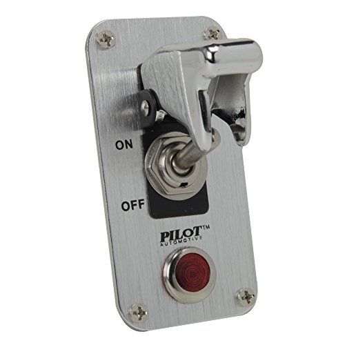
Main power switch: https://www.amazon.ca/Pilot-PLSW26-Safety-Racing-Toggle/dp/B000GTMUUI
Momentary Switch to activate the coil ONLY while pressed: https://www.amazon.ca/Ulincos-U16A1-Black-Button-Switch/dp/B015X34IP6
You'll also need some 18ga stranded wire, an enclosure, and some soldering skills/equipment.
You bet: Pilot Automotive Chrome Safety Cover Toggle Switch with Red Indicator Light (PL-SW52CR) https://www.amazon.com/dp/B00AWYCAJS/ref=cm_sw_r_cp_awd_Sp0FwbW83Y7QV
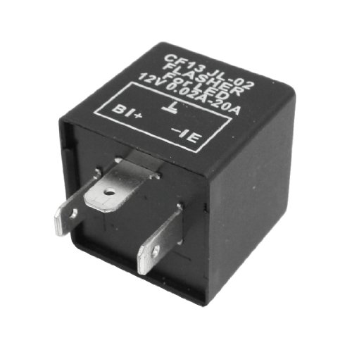
Yes, basically any standard 2 wire banana plug turn signals will fit in the front and rear. You will also need to get an led flasher. I have these on my front. This flasher relay should work.
So here's my project I've been working on for the past couple of weeks. I'm sure you can adapt this to a 2 motor lift setup (just add 4 more relays), or to another AC motor appliance. Here are the links for the key parts from Amazon:
Remote -$10.00
Relays -$7.00 x 4
Power Switch -$6.55
Box -$18.50
The whole thing came to about $75 and that's compared with $400 for a commercial one.
Edit: added the links for the parts
Edit 2: Correction to diagram
So here is my 2018 MT-09 and the mods I have. Various pictures, at different stages.
Newer pics
Older pic
Mods:
akrapovic exhaust w/ ECU flashed by vcyclenut
MZS Bar End Mirrors (not put on yet)
MZS Short levers
Progrip 724BlackRed 724 Superbike Grips
Windscreen
K-Tech RCU Razor-R Rear Shock
TST flush mount turn signals
TST Fender eliminator
Blaster LED integrated taillight
T-Rex frame sliders
Red intake stickers
Auxiliary lighting
Switch for aux lighting
wiring harness for aux lighting
Radiator guard
Corbin seat
Don't install resistors, this is how people set cars on fire. Instead get an [LED Flasher Relay] (http://www.amazon.com/uxcell%C2%AE-Vehicle-Blinker-Flasher-0-02-20A/dp/B00BLZ9XQK/ref=sr_1_1?ie=UTF8&qid=1463067876&sr=8-1&keywords=led+flasher+relay) this solves the problem at the source and doesn't require any modification of the factory loom.
three options:
Do you have a cable box or any other device that makes heat 24/7? If so, you might consider wiring up the fans to run 24/7. That's also the simplest way to wire them. Lower temperatures are good for electronic longevity. Fans wear out in a few years, but are cheap to replace compared to a PS4 or receiver.
If you want to trigger them off your receiver, that's pretty easy to do. Most likely your receiver can't power the fans directly (most 12V trigger outputs are 200-500mA output). Some receivers have a switched 120V outlet on the back, which makes this really easy, you just plug the fans in.
Fans can draw anywhere from 160mA (0.16A) to 600mA+ (0.6A)
The Antec fan you linked doesn't have a spec listed for power draw, but typically very quiet fans are below 300 mA.
If your total fan power draw (add together all fans) is less than 90% of the power your receiver can output, you can hook the fans up directly.
If your total power draw exceeds 90% of the rated output of your receiver, you need to use a relay to power the fans.
Here is a relay board that will work.
Here is the same thing but shipped free (probably from China, may be slow)
You'd also need a 12V power supply that provides enough current to run all your fans together.
Here are USB Fans - plug straight into PS4 or TV, and they turn on when the device powers up.
You could also use a 5V relay to control 12V fans from the PS4 usb if you wanted. Or use the TV's USB to trigger the fans whenever the TV is on.
Here is a plug and play thermally controlled fan setup
I'd plan on using both fans as exhaust on the top shelf. Just make air inlet holes in the bottom. Typically you want 30%-50% more inlet volume than outlet volume if you can get it. Remember all the cracks along the doors and edges will let air in as well. Making an air path across the front of the shelf by trimming is a fine idea.
So, step 1, decide when you need the cooling system to turn on - PS4, receiver, tv, 24/7, or other (such as temperature).
Then I can tell you how to use that device to turn it on.
Does this work as a battery isolator?
https://www.amazon.com/gp/product/B00WMBV05Y/ref=oh_aui_detailpage_o02_s00?ie=UTF8&psc=1
What is the advantage of a more expensive device over this simple relay?
I dreamed this up after I had replaced the angle sensor & shift motor, then realized it was an intermittent problem with the ESP module. I installed this last night on a 2001 450 foreman. The relays used can be ordered from Amazon for $9.87 relay kit
You should add a small reset button right next to it!
Use a race switch or a whole race start switch panel!
Edit: Also found this cool thing.
I started off with an empty project box that I bought off amazon. I drilled out all the holes for the button placements and wired it all myself.
I'm running 2 Reyann Zero Delay USB Encoders as the brains for the buttons.
(I'd like to eventually learn to use an arduino)
The buttons are standard arcade buttons, and the switches are momentary toggle switches.
​
Here is everything I put in the box.
The Box:
https://www.amazon.com/gp/product/B005T98PQS/ref=ppx_yo_dt_b_asin_title_o00_s00?ie=UTF8&psc=1
The Reyann Zero Delay:
https://www.amazon.com/gp/product/B00UUROWWK/ref=ppx_yo_dt_b_asin_title_o02_s00?ie=UTF8&psc=1
Arcade Buttons:
https://www.amazon.com/EG-STARTS-Illuminated-Joystick-Raspberry/dp/B06Y29LBJ4/ref=sr_1_48?keywords=led+arcade+buttons&qid=1572284635&sr=8-48
Smaller Toggles:
https://www.amazon.com/gp/product/B06XGB77DD/ref=ppx_yo_dt_b_asin_title_o03_s00?ie=UTF8&psc=1
Larger toggles:
https://www.amazon.com/gp/product/B07HS4HBD3/ref=ppx_yo_dt_b_asin_title_o03_s00?ie=UTF8&psc=1
Happy to see good progress on this project!
>Opted for a push model to save space, just gonna attach a cam or something to the pin.
Just to be clear, the model you've linked will pull when given power and return to static without power. I'm not to sure what your goal with a cam is, maybe I'm envisioning the wrong item, but you should be able to attach the Thunder B pin directly to the actuator's plunger.
> I don't have a ton of faith in the range on that remote, so...any suggestions to hook it up to my cell phone without still having to be within wifi range, which will be even worse than the remote's range? Or, how to extend the range on the remote?
It is my understanding, albeit probably inaccurate, that Radio range is directly proportional to antenna length with a weighting factor from the power supplied. So you might be able to splice a longer antenna, but I think there will be diminishing returns after a point. You'll want to investigate that further.
>Basically, I don't want someone to pick up the device in-game and have me detonate it without realizing it's in their backpack, so i'm giving them an option to defuse it. This will be in line with the battery so that everything is 100% cut off, no ifs, ands, or buts.
This is a very important safety feature and I'm glad to see that you're electing to go about it this way. However, I would suggest something like this with a switch cover to make sure that it can't be accidentally turned on. Also, it's a default off now which allows players to turn it on manually (or game organizers) and also to give a visual reminder, though small, that the system is active.
All said, that's a fair price point
IMO, being a professional 12v installer, a simple relay rated for your application is the easiest, safest way to accomplish what you're trying to do.
terminal 86 to ground, 85 to a switched ignition 12v power source, and the two other terminals connect one battery bank to the other.
This is a proven setup up for years on cars with hydraulics or demanding audio systems where multiple batteries are installed in a particular vehicle.
Hi /u/overlyapologeticguy! /u/bntyhntrqueen made me do this.
I just added this to my wishlist. Why, you might ask? Becuase I want to build an electrical light panel and what good would that be without an awesome EMO switch?
(I also added a master switch to the list but I figure I'm supposed to pick one thing to add to your list. So I went with that.)
http://www.amazon.com/MICTUNING-Toyota-Switch-Connector-Symbol/dp/B0117B1J3W
Module and Coil
ZVS Driver Module,5V-12V ZVS Low... https://www.amazon.com/dp/B01CNM24YM?ref=ppx_pop_mob_ap_share
12V 20A LED switch with cover
AutoEC New 12V/20A Red LED Illuminated On/off SPST Car Automotive Toggle Switch Button https://www.amazon.com/dp/B012IHZW4G/ref=cm_sw_r_cp_apa_i_YIOWCbX59GG36
18 gauge wire
BNTECHGO 18 Gauge Silicone Wire... https://www.amazon.com/dp/B01AQOI36M?ref=ppx_pop_mob_ap_share
12v 6a power supply
AspenTek Us Plug Dc 12v Power... https://www.amazon.com/dp/B00GU63ICU?ref=ppx_pop_mob_ap_share
Then I used three spade connectors to attach the wires to the switch, which you can get from walmart
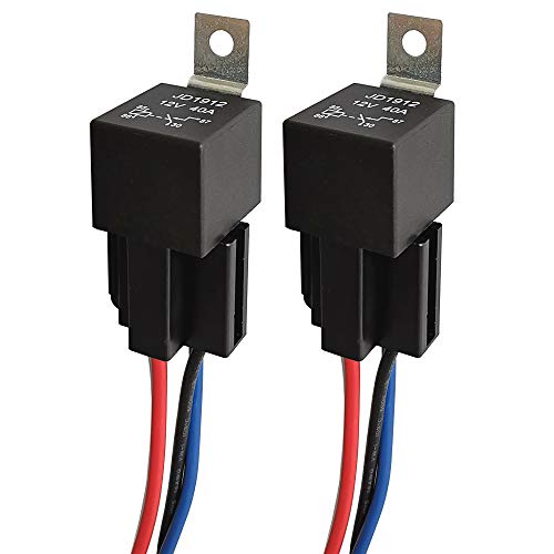
ARTGEAR JD1912 Car Relay Harness 12V 40A 4 Pin SPST Harness Sockets with Color-Labeled Wires for Automotive Truck Van Motorcycle Boat (Pack of 2) https://www.amazon.com/dp/B078T8CMF6/ref=cm_sw_r_cp_apa_i_s7EQCbJ57W1HB
Thanks! I'm in Los Angeles, only electronic components place I can think of is Fry's Electronics: www.frys.com
Would something like this work? https://www.amazon.com/SMAKN%C2%AE-SRD-12VDC-SL-C-Channel-Level-Module/dp/B00MMW0XWY/ref=pd_sim_60_3?ie=UTF8&psc=1&refRID=VZ0TCJ9326VS28VJSDEJ
Thanks again for your help.
Pilot PLSW26 Safety Cover Racing Toggle Switch by Pilot Automotive
Clearview Child Resistant, Handicap Accessible Switch Guard by Clearview
I will take one this evening, I'm not near the project at the moment.
The switch has three pins. Here they are: https://www.amazon.com/gp/product/B06XGB77DD/ref=ppx_yo_dt_b_asin_title_o00_s00?ie=UTF8&psc=1
I've used a number of these in my Tahoe, but I've never done something like this. So to be clear the switch that you have has 3 positions? on-off-on? 2 separate 'on' positions? If that is the case I think you could do this by just adding a 'bosch style' relay off of Amazon by running one wire out of your switch directly to the light bar, and from the other side of the switch running to the relay's trigger (86). The dome light will be ran to the relay's source (30). Your light bar would also have another wire running out of relay output (87). Everything would then ground to the frame (or a neutral) from the light bar and from the relay (85). Relay output (87a) would be capped off. The appropriate fuses would be needed before the switch and maybe even between the relay and the light bar. I believe this should work.
https://www.amazon.com/gp/product/B074FSZWVT/ref=ppx_yo_dt_b_search_asin_title?ie=UTF8&psc=1
Here is the mobile version of your link
Those wires are going to be battery, flasher out, and ground. For standard filament bulbs, just buy a 2 prong standard mechanical relay and leave the ground disconnected. If you upgrade to LED bulbs, switching to a load independent relay (usually 3 prongs) will fix the fast blink issue.
In the 3 prong the coil side seeks ground for discharge through the additional ground, otherwise it has to discharge through the circuit. Because the load (resistance) is low with LED bulbs, the capacitor that controls the coil latch timing can discharge really fast and the flasher blinks fast or not at all. There are some electronic relays without a standard coil/cap that have a rheostat in them that allows you to adjust the discharge load. Those will be 2 prong - they discharge through the bulbs/circuit. The standard mechanical relays are available at any auto parts store.
Electronic solid state 2 prong with adjustable load:
https://www.amazon.com/AUDEW-Electronic-Signal-Flasher-Motorcycle/dp/B011BTMDQM/ref=sr_1_4?ie=UTF8&qid=1493815500&sr=8-4&keywords=electronic+flasher
Standard mechanical coil 2 prong:
https://www.amazon.com/Bussmann-NO-552-12-8-Thermal-Flasher/dp/B000GKAZCW/ref=sr_1_1?ie=UTF8&qid=1493815609&sr=8-1&keywords=12v+flasher
3 prong with load independent grounded coil (my preferred type - these still need some load to function):
https://www.amazon.com/uxcell-Vehicle-Blinker-Flasher-0-02-20A/dp/B00BLZ9XQK/ref=pd_sbs_263_2?_encoding=UTF8&pd_rd_i=B00BLZ9XQK&pd_rd_r=B9EGDRDCQ81ZH9VWKT7A&pd_rd_w=SRsBN&pd_rd_wg=UBlTA&psc=1&refRID=B9EGDRDCQ81ZH9VWKT7A
so... not much help, but what I did find is that it's a big line of products from something called "Alpine Tech" or "Alpinetech" The ATI is an indicator for that. The part number is listed on the item as well. They also have an Amazon store.
I couldn't find any other info about anything called Alpine Tech or ATI in regards to who might actually be 'making' the switch.
Based on the item listings I've seen directly from them on Amazon, I'm guessing they're a random amazon shop that's not a real business and just buys up chinese stuff and re-sells it (not that there's anything wrong with that... he said as he looks at his shelf full of chinese stuff).
Here's teh Amazon Store
http://www.amazon.com/gp/node/index.html?ie=UTF8&marketplaceID=ATVPDKIKX0DER&me=A1ZFJY6YSKB3ZG&merchant=A1ZFJY6YSKB3ZG&redirect=true
And here's what you were looking for I think.
http://www.amazon.com/Alpinetech-Anti-Vandal-Stainless-Momentary-Terminal/dp/B00MB5CXKC/ref=sr_1_1?m=A1ZFJY6YSKB3ZG&s=merchant-items&ie=UTF8&qid=1419086456&sr=1-1&keywords=12mm&pebp=1419086481061
I don't see a 12mm version that has the same actuator as what you linked, only the domed version. But I'm pretty sure that's the same back end, smaller panel cut out, same depth.
The switch, or more precisely the circuit board for the switch, came from here: http://www.mausberrycircuits.com/collections/frontpage
Pick the one that fits your needs. You'll also need an actual switch; I grabbed a momentary switch from Radio Shack. Again, pick one that fits your needs. You can use a momentary, slide, toggle, pushbutton... the Mausberry doesn't care. You'll also connect the Mausberry to 2 pins on the Pi and download s script from Mausberry that executes when the switch is flipped (thus the orderly shutdown). You know how the Pi's red light stays on when you shut it down via a command? The Mausberry completely shuts off the power to the Pi, so no more red light.
I've had the buck converter for a few years from another unfinished project. It accepts up to 30 volts input, and output is adjustable via a tiny screw. I have mine set to output 5.15v. It will output up to 3 amps. I remember it came from eBay via a slow boat from China, but I'm sure Amazon has the same thing. It doesn't have to be adjustable, as long as it outputs 5ish volts.
The relay I think came from Adafruit. It activates (closes the circuit) when one of the Pi's power pins (i think I used pin 1) is hot. So if the Pi is ON, the hub is ON and vice versa. When activated, it allows power to flow from the buck converter to the USB hub. The USB hub then powers the SDR's and the WiFi dongle.
The hub itself is a cheap unpowered hub from the radio shack clearance rack. I stripped it down to the bare board and soldered wires to the pos and neg to make it powered.
I wanted a hub so I could offload the peripheral's power requirements from the Pi to the buck converter. I just don't think the Pi really likes pushing that much power to its peripherals.
The GPS/AHRS gets power via the Pi's pins as per the normal connection, but I had considered powering it from the relay.
The reason I went to this length for the power is because in the beginning, it was hard for me to find a 5v power source that could provide the necessary power via a USB cable. Either the portable battery was lacking, or the cable was lacking, or the 12v USB adapter was lacking. So the obvious solution to me was to accept ship's power (12v-24v) and convert it to 5v myself. From there it was an easy decision to split out the power and ease the strain on the Pi. I have 12v power easily available in the Mooney and I have the portable 12v ammo box (in the pictures) when I fly in other planes, so in my situation a solid 12v source made better sense than an iffy 5v source.
Caveat emptor: With this setup, you are no longer building a "cheap" ADS-B box, but rather a darn good, reliable one at a very reasonable price. And should something inside ever fail, it's a cheap matter of replacing the bad component rather than the whole setup. WIN! I am ever grateful to the software developers.
EDIT: here's a link to the relay: http://www.amazon.com/gp/product/B009T2M012?ref_=cm_sw_r_awd_HYZBwb5RRB29
This looks like the Buck converter. Turn the tiny brass screw to adjust the output voltage: http://www.amazon.com/gp/product/B00TMFKJ9Q?ref_=cm_sw_r_awd_Y4ZBwbC5J8VK9
As others have said, a relay is what you need. I have this one. It's designed with the Arduino in mind and can switch a 250 VAC , 10 A load, which should be plenty for your coffee maker. As a bonus, the trigger current is only 5 mA, so you can plug it directly into a digital pin and have it work. To turn the relay on, use:
digitalWrite(<pin number>, HIGH)
To turn it off use:
digitalWrite(<pin number>, LOW)
It requires 3 connections: 5V, GND, and signal.
I added fog lamps to my bike using the following parts:
lights: https://www.superbrightleds.com/moreinfo/led-light-pods/10w-mini-aux-2in-modular-led-off-road-work-light/1699/12998/
switch: https://smile.amazon.com/dp/B0779S35VB/ref=cm_sw_em_r_mt_dp_U_wL2ACbWR4NQZ1
&#x200B;
I powered my relay with Aux DC 1. Check out pages 88-91, 552-553 of the shop manual
&#x200B;
Her's some helpful files:
Schematic: http://i66.tinypic.com/vi1ye9.png
Bracket: https://www.scribd.com/document/399947695/Fog-Lamp-Bracket
The Relay I cut up: https://smile.amazon.com/dp/B07B51PVJV/ref=cm_sw_em_r_mt_dp_U_AQ2ACbSQ82139
&#x200B;
Not OP, but I used a cheap Gang switch from Amazon to control my ditch and wheel well lights. This one to be exact: 80-Amp On/Off Switch Box [20A Rocker Switches] [LED Backlit] [12AWG Input Wire] 12V SPST 6-Gang Rocker Switch Panel for Automotive https://www.amazon.com/dp/B07M9X7N74/ref=cm_sw_r_cp_apa_i_gLTxDbDAFRWPG
Sort of. There's sort of a progression going on. It's a good idea to ensure you can cut the power between the two manually as a safeguard.
I used this
last time with a fuse on each battery, and just kept the accessories live to the house battery full-time. Turned it on when I wanted to charge or the odd case of boosting my starter battery from the house. Dead-simple hook up, I just had to pay attention to when I should have it on or not. Mostly cut it on before I start the vehicle, watch the dash voltmeter to know when everything's charged, then cut it off before I start using the house without the motor running.
I'm getting this one next time to replace the one above. I'll have the common on the accessories, and be able to run them off of the starter, the house, or both. "both" would also be used to charge the house off the alternator, and I'll have it there almost all the time, with the addition of a VSR (below). It also has an "off", in which nothing is connected to anything. You'd still want to wait until the engine is running to re-charge a dead house battery, and switch it to only "2" to keep from draining the starter battery, unless you install one of the next two items.
This makes a nice addition wired right alongside either switch. Tells you how much juice each battery has.
To keep everything 100% un-screw-up-able, this is going to go between my starter battery positive and my new manual isolator switch in back. If either side gets to charging voltage, it will connect to the other side. That means the alternator will always charge the starter battery, but also charge the house battery AND if I connect a charger to the house battery (like a generator or plugging in to shore; solar that fits on a van would take several days to charge a battery from dead to van-crankable), then it will automatically charge and maintain the starter battery, too. Neither can drain the other past the point it wouldn't crank the van.
Charging relays are much cheaper than a VSR, and are automatic in a more rudimentary way. This will do the job fine for most cases, and is a little less expensive than a VSR. The big lugs on it hook up just like the two on the VSR above, except it's not automatic - you hook the small poles up to stuff to tell it when to connect the big lugs. The small positive goes to the other, smaller wire going into the alternator, only allowing it to connect if the alternator is charging. The small negative can go straight to the large negative, but I'd run it through a small switch in the dashboard somewhere (and the other side of that switch back to the large negative lug) to allow me to disable charging house battery off the alternator. it's a decent blend of manual and automatic control, with a relatively tiny price tag. This pretty much needs to go under the hood, though, whereas the VSR could actually go in the power center or under the hood. Remember that either would go on the 4 gauge between starter battery and rear isolator, if present; it's the longest fat-wire in the whole system. some people skip the manual isolator switch altogether, and just go with a VSR or charging relay.
Only because I happen to have one of the first switches linked here already, I'd install it between the large lugs of the VSR or charging relay, to bypass it manually. If I didn't already have one, I'd just count on using a set of jumper cables to do that in the rare case I should need to turn that switch on.
I threw a button for my front LED lights in there. Great button and works perfect. My only complaint is I got the white version and it's SUPER bright. One day I'll quit being lazy and put a resistor on it to dim it down a bit. Would also be nice to find a way to color match the orange color all the rest of the buttons are.
But overall, button works great.
Ooh, that does look like a more simplified circuit.
Yeah, can't locate a suitable DPDT microswitch, and I don't think 2 SPDTs are thin enough to fit in the handle, so I'm liking that DPDT relay idea. Do you think an automotive one such as this would be suitable?
As for the selector switch, I've got a nice DPDT ON-OFF-ON rocker that I'm planning to use.
Thanks again for all of this excellent advice, I cannot easily express how much I appreciate it. (But stop helping strangers on the internet and get prepping for finals!! Also, good luck!)
Yes, also, you might want to consider adding a relay and fuse block for accessories:
[Relay]( https://www.amazon.com/dp/B078T8CMF6/ref=cm_sw_r_tw_dp_U_x_bqmiDbBMSEFWX via @amazon)
[Fuse Block](https://www.amazon.com/dp/B00QMTAZ1W/ref=cm_sw_r_tw_dp_U_x_yrmiDbE7ZJ4HY via @amazon)
Wiring Guide
The fuse block should be under the seat/tail in a protected area.
Yes! That does make sense. I was looking on Amazon, and came across this relay. with the drawings, should be similar. Off with a positive trigger.
https://www.amazon.com/ONLINE-LED-STORE-Pack-Interlocking/dp/B01KVZ2MU4?ref_=fsclp_pl_dp_2
1.
Which wires specifically? In general, I was planning on going for heat-shrink solder terminal connectors and crimp connectors.
One of the reasons I posted this is because there are quite a few connectors and I am still not entirely 100% sure what I need. Obviously when screwing something in to a screw terminal block, the ring crimp connectors. But when joining wires, I would prefer to use the heat-shrink-solder type, but there are also butts and blades (heh).
I bought this set of terminals, figured I'd need them anyways: Assorted crimp terminals
I am probably going to buy this set of solder terminals: Fancy solder terminals
I am pretty good at soldering (though usually circuit boards, not automotive wires, hence not entirely knowing what to do.) I have easy access to a heat gun as well.
2.
Well, both - the breaker goes on the battery, and it sets the maximum amperage for the entire new fuse block and everything attached to it. The fuses go for each individual circuit. I want to use just one fuse for each circuit, instead of having several different circuits sitting on the same fuse, largely for my own desire for neatness and debug-ability. I could have one main fuse instead of the main breaker, but I figure that they will serve the same function and I may as well go for the re-usable option.
I was going to go for this breaker: Fat breaker
That said, I bought this fuse kit, which includes up to a 35A fuse, which will be more than enough. I also bought this fuse holder, in case I decide to use one main fuse instead of one main breaker. (I figured I'd need both of these anyways for some project, may as well get them even if I don't use them right now.)
Fuse Kit
In-line Fuse Holder
---
In general, I think my system will basically look like this:
Battery 12V + Breaker = safe 12V
Save 12V + ignition 12V (do I need a fuse here?) + Relay = ignition-switched 12V
Ignition-hot 12V + Fuse Block + ATC/ATO Fuses = eight fused circuits
Fused circuits, obviously, feeding from above. I will probably add a 20A switch in line with high-power circuits, just in case, as an emergency switch.
Fused circuits will terminate at something like this Ground Bar.
&nbsp;
What do you think of this proposed setup?
I do realize that it's kind of overkill for what I want.
But you can probably agree that overkill is better than your car burning down!
Is there any reason why you wouldn't just buy a normal 12v relay and run it to the ignition switch from the fuse panel instead of spending $60 on one with a relay built in? For example use these:
https://www.amazon.com/OLS-6-Way-Blade-Indicator-Protection/dp/B00QMTAZ1W/ref=sr_1_3?ie=UTF8&amp;qid=1497658098&amp;sr=8-3&amp;keywords=fuse+panel
https://www.amazon.com/OLS-Split-Charge-Relay-Switch/dp/B01MYPTVJD/ref=sr_1_1?ie=UTF8&amp;qid=1497658136&amp;sr=8-1-spons&amp;keywords=12v+relay&amp;psc=1
Got a handful here and there but mostly aesthetic mods. I've got:
Bully Fuel Controller by GMan
Kuryakyn Hypercharger
Integrated Tail Light
Electronic Flasher
[Switchback Turn Signals] (https://www.amazon.com/dp/B076GLLS3T?ref=ppx_pop_mob_ap_share)
I have a few more on my list to-do but I broke my hand so I'm off the bike for another 3 weeks ),:
80-Amp On/Off Switch Box [20A Rocker Switches] [LED Backlit] [12AWG Input Wire] 12V SPST 6-Gang Rocker Switch Panel for Automotive https://www.amazon.com/dp/B07M9X7N74/ref=cm_sw_r_cp_api_i_L215Cb25DHG61
I haven’t measured it out yet to make sure it’ll fit. Worse case scenario I’ll use the 4 switch version.
If you live in an area where they salt the roads look into sealed relays. I’ve had quite a few fail over the years from rust even when tucked up under the hood. And I agree with the other guy make sure the wiring can handle the current draw but also the relays.
I picked these up for my fog and driving lights.
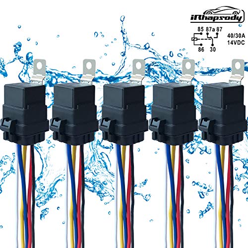
5 PACK 40/30 AMP Waterproof Relay and Harness - Heavy Duty 12 AWG Wiring Harness - 12V DC 5-PIN SPDT Bosch Style Automotive Relay - MAX 14V DC
https://www.amazon.com/dp/B074FSZWVT/ref=cm_sw_r_cp_api_r5RTBbEPD9G2K
Here are my lights.
https://m.imgur.com/nkpEsKQ
Thanks!
Did some quick research and found some relays that appear to be pretty straight forward.
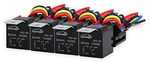
I already bought and have these however: https://www.amazon.com/Pack-EPAuto-Relay-Harness-Bosch/dp/B072QXDZRD/ref=sr_1_4?ie=UTF8&qid=1550813873&sr=8-4&keywords=12v+bosch+style+relay
&#x200B;
Is it possible to make it work with these? Would it be as simple as having my "orange circuit" on the 30 and 87 pin and push the 12v to the 86 and ground to the 85?
&#x200B;
If not, would this work?
https://www.amazon.com/Support-Relay-Spst-4pin-Socket/dp/B00RVCFNCK/ref=sr_1_10_sspa?ie=UTF8&qid=1550819958&sr=8-10-spons&keywords=SPST-NC+12v&psc=1
&#x200B;
edit: I put a 10k resistor on the circuit so I could test the open and close when 12v was introduced. I used the example explained above, under the first produt link, as my circuit. When there is 12v power applied, the circuit is closed and it reads 10k. I need to reverse that, where the circuit is always closed without power and only opened when power is introduced to the relay. Do I have the wrong relay?
&#x200B;
Thank you so much!
http://www.amazon.com/gp/product/B00MB5CXKC/ref=oh_aui_detailpage_o01_s00?ie=UTF8&amp;psc=1 this is where i got it, yes it is 3 amps.... not really sure what i would need in a switch.