Best automotive switches & buttons according to redditors
We found 211 Reddit comments discussing the best automotive switches & buttons. We ranked the 141 resulting products by number of redditors who mentioned them. Here are the top 20.
We found 211 Reddit comments discussing the best automotive switches & buttons. We ranked the 141 resulting products by number of redditors who mentioned them. Here are the top 20.


![6-Gang 12V Rocker Switch Box [60 Amp Max.] [12 AWG Wires][12 Volt DC] SPST On/Off Rocker Toggle Switch Panel Box for Auto Automotive Lights Car Marine Boat Truck Vehicles & More](https://m.media-amazon.com/images/I/51HOQGd94vL.jpg)


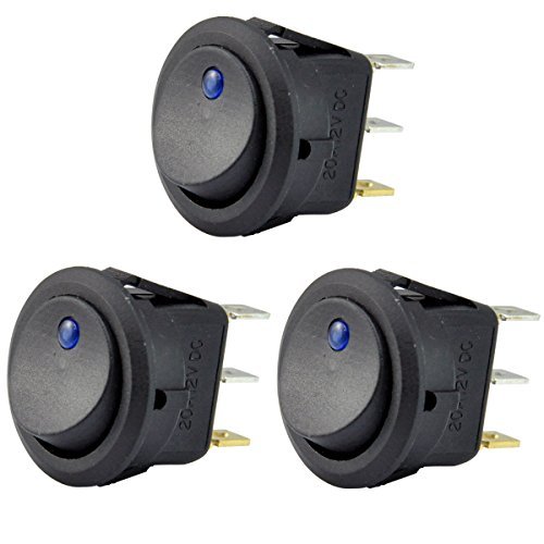
ESUPPORT 12V 20A Red Cover Rocker Toggle Switch SPST ON/Off Car Truck Boat 2Pin Pack of 5 https://www.amazon.com/dp/B0154JY8OA/ref=cm_sw_r_cp_api_i_0v0RDb8XB2S8T
https://rover.ebay.com/rover/0/0/0?mpre=https%3A%2F%2Fwww.ebay.com%2Fulk%2Fitm%2F352491845873
There ya go
GOLDEDIT: omg my first gold! Thanks anon!
THE TRIGGER WIRE CAN BE CONNECTED TO Vin + or Vout +
How it looks now: https://i.imgur.com/Xmro9I5.jpg
Parts list (canadian, but you can find everything on amazon and/or ebay, or locally):
Heater Board and Coil: https://www.amazon.ca/BAQI-5V-12V-Voltage-Induction-Heating/dp/B0747NBTBX
MOSFET Relay (for operating the momentary switch): https://www.amazon.ca/DROK-Transistor-Driving-Electronic-Controller/dp/B01J78FX9S (if you want to do this project with NO SOLDERING you could get this higher wattage MOSFET relay)
Power Supply (or if you have one from an xbox 360 it'll work) This one also includes the female jack: https://www.amazon.ca/Signcomplex-Supply-Transformer-Switching-Adapter/dp/B075R3RW6J
Glass tube: https://www.amazon.ca/Dunlop-202-Dun-Bottleneck-Slide-Reg/dp/B0009EQMZE
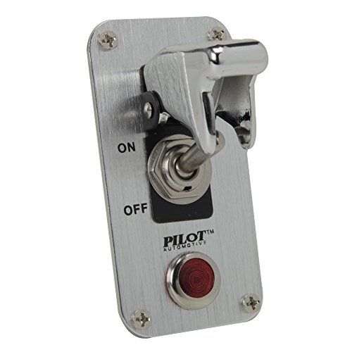
Main power switch: https://www.amazon.ca/Pilot-PLSW26-Safety-Racing-Toggle/dp/B000GTMUUI
Momentary Switch to activate the coil ONLY while pressed: https://www.amazon.ca/Ulincos-U16A1-Black-Button-Switch/dp/B015X34IP6
You'll also need some 18ga stranded wire, an enclosure, and some soldering skills/equipment.
You bet: Pilot Automotive Chrome Safety Cover Toggle Switch with Red Indicator Light (PL-SW52CR) https://www.amazon.com/dp/B00AWYCAJS/ref=cm_sw_r_cp_awd_Sp0FwbW83Y7QV
12V/5V is nothing for a off the shelf switch. If you want to get semi-fancy, you can take one of our 5 1/2 in bay covers and drill out the appropriate sized whole and install 4 toggle switches. Maybe 5 if you want a master kill switch (space permitting).
Here is a 5-pack for $10: https://www.amazon.com/Nilight-Rocker-Toggle-Switch-Waterproof/dp/B078KBC5VH/
Get some PWM fan header cables (https://www.amazon.com/CRJ-Black-Sleeved-Splitter-Adapter/dp/B075H6HT8J/ for instance). you just need enough extra cable to go from the PWM header on the Mobo to the switch. Make sure the PWM lead (yellow i think?) and Negative is still wired to the fan. You still would like to monitor the RPM I am sure. Simply wire each 12V+ lead to the switches.
Even better, get some switches with an LED so that you can tell when they are on: https://www.amazon.com/Lighted-Rocker-Toggle-Linkstyle-Vehicles/dp/B0776QXX21
Edit: Cant confirm this... But this doc seems to show some or all of the PWM specification if you want to dig further. https://www.handsontec.com/pdf_files/4_Wire_PWM_Spec.pdf
internal shot
Parts list:
Tools:
STL for 3d printing:
All three files
Wiring diagram:
Terrible MS paint Diagram
I don't know if it'll fit directly into the space but you can get a a pilot switch and either dremel out a hole in the oem switch panel or you can take the empty panel out and use some kind of filler to make the switch snug in the spot. I did something similar for my roof lights, put the switch in the spot and used a cut up magnet wedged in the crevasses to make it snug, and it looks pretty good
http://www.amazon.com/GTR-Red-Start-Button-2009/dp/B004D0I11S
Actually only a bit under $50 for the button itself
After seeing a couple posts of people's custom button boxes on reddit I knew I had found my next project. I've been doing quite a bit of Arduino and small electronics lately, and this was the perfect fit. So off I went to Amazon, ordered a bunch of stuff I thought might be cool / useful and started piecing things together. Took a few weekends of working on it here and there, the most time consuming part just being tediously soldering and wiring the 38 inputs.
​
Was originally going to set it into some sort of project enclosure, but ended up getting impatient and just mounting it to two pieces of plywood with some feet. It added enough heft to it that I can lift the switch guard and rotate the somewhat stiff selector without issue. Eventually I'll get a better enclosure for it, probably grab one off of Hammond mfg or get someone with a larger 3D printer to make one. The Engine Start and black/red button (that I'm going to use for quantum jump) have leds in them that I don't currently have hooked up to the Arduino, but once we get some sort of API into Star Citizen hopefully I can tie them to engine state and jump spool/ready state.
​
The controls are:
Power on, flight ready, 3 misc buttons, zoom rotary encoder, 3 misc buttons, quantum spool, quantum jump
Hat switch + center for shield distribution and reset, engine, shield, and thruster power switches, power distribution profile selector, misc selector
Flare Fire button, flare select, 7 misc toggle switches, self destruct switch, eject switch.
​
I mapped everything to a button in the Arduino code (no rotary encoder as zoom in this screenshot) so that I can easily bind to functions in Star Citizen. Unfortunately without an API this means the switch positions can get out of sync with the actual ship status easily. If by the time of release / they make an API there still isn't a way to read / set state by API then I'll probably make a new version with only toggle buttons.
​
Code Libraries
PCF8574_library for interfacing with the IO expanders
- https://github.com/xreef/PCF8574_library
ArduinoJoystickLibrary for emulating a joystick on windows
- https://github.com/MHeironimus/ArduinoJoystickLibrary/
​
Useful Instructables
Joystick Library
- https://www.instructables.com/id/Create-a-Joystick-Using-the-Arduino-Joystick-Libra/
PCF8574
- https://www.instructables.com/id/PCF8574-GPIO-Extender-With-Arduino-and-NodeMCU/
​
Parts List
1 Terminal Expansion Board - https://www.amazon.com/gp/product/B07PGDWJ2V
3 PCF8574 IO Expansion Board - https://www.amazon.com/gp/product/B07B95LMLQ
1 Rotary Encoder - https://www.amazon.com/gp/product/B07DM2YMT4
1 4 Position Rotary Selector - https://www.amazon.com/gp/product/B07JN2967L
1 Red Ring Momentary Push Button - https://www.amazon.com/gp/product/B017ILTX60
1 Engine Start Momentary Push Button - https://www.amazon.com/gp/product/B07MK2394L
5 Heavy Duty Toggle Switch - https://www.amazon.com/gp/product/B078KBC5VH
1 12 Position Rotary Switch - https://www.amazon.com/gp/product/B074WMC9C8
1 5-Channel Rocker - https://www.amazon.com/gp/product/B07K5PFPNC
1 Arduino Micro - https://www.amazon.com/gp/product/B00AFY2S56
7 Red/Black Momentary Push Buttons - https://www.amazon.com/gp/product/B07BD2D96W
2 Red Cover Toggle Switches - https://www.amazon.com/gp/product/B07BD2D96W
8 Small Toggle Switches - https://www.amazon.com/gp/product/B013DZB6CO
So here is my 2018 MT-09 and the mods I have. Various pictures, at different stages.
Newer pics
Older pic
Mods:
akrapovic exhaust w/ ECU flashed by vcyclenut
MZS Bar End Mirrors (not put on yet)
MZS Short levers
Progrip 724BlackRed 724 Superbike Grips
Windscreen
K-Tech RCU Razor-R Rear Shock
TST flush mount turn signals
TST Fender eliminator
Blaster LED integrated taillight
T-Rex frame sliders
Red intake stickers
Auxiliary lighting
Switch for aux lighting
wiring harness for aux lighting
Radiator guard
Corbin seat
three options:
You could get one of these which really cleans up the inside
You should add a small reset button right next to it!
Use a race switch or a whole race start switch panel!
Edit: Also found this cool thing.
Jumping the e-brake pin is not a difficult thing to do, and a local shop will definitely do it for you.
Source: guy with jumped e-brake pin that was done by a local car audio shop.
edit: there's even this thing http://www.amazon.com/Override-Automatic-AppRadio2-SPH-DA100-APPRADIO/dp/B008NQL00W
http://www.amazon.com/MICTUNING-Toyota-Switch-Connector-Symbol/dp/B0117B1J3W
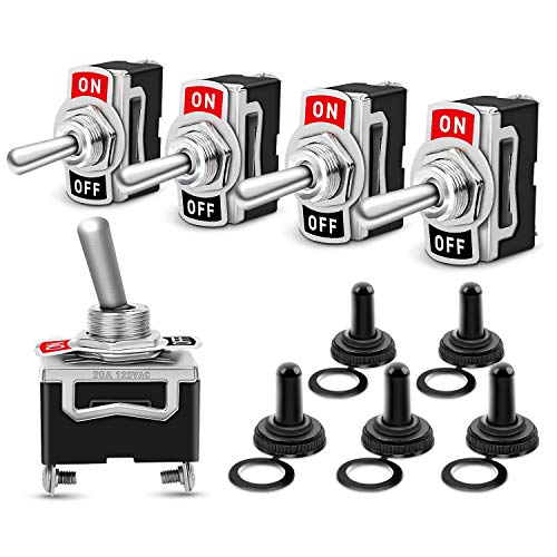
These switches are petty cool: https://www.amazon.com/dp/B0154JY8OA/ref=cm_sw_r_cp_apa_i_JJ7TCbCG3N2A3
shopping list for DIY;
http://www.amazon.com/gp/product/B00I11MV52
http://www.amazon.com/gp/product/B00GWF22KS
http://www.amazon.com/gp/product/B007B8JMZI
http://www.amazon.com/Energizer-A23-Battery-Volt-Batteries/dp/B00ICS8OF0/
+whatever LED circuit you want.
I started off with an empty project box that I bought off amazon. I drilled out all the holes for the button placements and wired it all myself.
I'm running 2 Reyann Zero Delay USB Encoders as the brains for the buttons.
(I'd like to eventually learn to use an arduino)
The buttons are standard arcade buttons, and the switches are momentary toggle switches.
​
Here is everything I put in the box.
The Box:
https://www.amazon.com/gp/product/B005T98PQS/ref=ppx_yo_dt_b_asin_title_o00_s00?ie=UTF8&psc=1
The Reyann Zero Delay:
https://www.amazon.com/gp/product/B00UUROWWK/ref=ppx_yo_dt_b_asin_title_o02_s00?ie=UTF8&psc=1
Arcade Buttons:
https://www.amazon.com/EG-STARTS-Illuminated-Joystick-Raspberry/dp/B06Y29LBJ4/ref=sr_1_48?keywords=led+arcade+buttons&qid=1572284635&sr=8-48
Smaller Toggles:
https://www.amazon.com/gp/product/B06XGB77DD/ref=ppx_yo_dt_b_asin_title_o03_s00?ie=UTF8&psc=1
Larger toggles:
https://www.amazon.com/gp/product/B07HS4HBD3/ref=ppx_yo_dt_b_asin_title_o03_s00?ie=UTF8&psc=1
Module and Coil
ZVS Driver Module,5V-12V ZVS Low... https://www.amazon.com/dp/B01CNM24YM?ref=ppx_pop_mob_ap_share
12V 20A LED switch with cover
AutoEC New 12V/20A Red LED Illuminated On/off SPST Car Automotive Toggle Switch Button https://www.amazon.com/dp/B012IHZW4G/ref=cm_sw_r_cp_apa_i_YIOWCbX59GG36
18 gauge wire
BNTECHGO 18 Gauge Silicone Wire... https://www.amazon.com/dp/B01AQOI36M?ref=ppx_pop_mob_ap_share
12v 6a power supply
AspenTek Us Plug Dc 12v Power... https://www.amazon.com/dp/B00GU63ICU?ref=ppx_pop_mob_ap_share
Then I used three spade connectors to attach the wires to the switch, which you can get from walmart
I used this charger with this USB charging cable to keep it charged up, this parking brake bypass relay, and this SlimPort adapter.
https://www.amazon.com/dp/B012IJ35VQ/ref=cm_sw_r_cp_apa_i_OJN-AbA3J0G0W
Something like this, of you want you can go to your local hardware store, they will have switches there, just tell them you need one rated for 12 volts and 10 amps. I did that because all the ones on Amazon are a little expensive for switches IMO
http://www.amazon.com/Rugged-Ridge-17235-58-A-Pillar-4-Switch/dp/B009X23B2U#customerReviews
The switches for the front dome/map lights wear out all the time. Very easy and cheap to swap. Four screws, ten minutes.
https://www.amazon.com/Dorman-924-798-Dome-Lamp-Switch/dp/B00FY81BUQ
It’s just an electrical connection. You’re basically going to bypass the +12v wire that activates the valve flaps from the control module with a +12v wire that is activated by an accessory source(think cigarette adapter, radio, etc.).
What I would do is use one of these:
https://www.amazon.com/AutoEC-Rocker-Toggle-Switch-Control/dp/B012IJ35VQ/ref=mp_s_a_1_6?keywords=12+volt+power+rocker+switch&qid=1566944665&s=gateway&sr=8-6
That way you can have it “always on” until you flip it into the other position, and have it managed by the control module. Essentially one of the connectors will go to the flap, the second one will be the +12v from the original source, and the third wire will be the +12v from a cigarette adapter (which should only be “on” when the ignition is on). It’s a bit more complicated than that since you’ll have to worry about heat shielding the wires, where they come into the cabin, and where you put the switch. You may have to remove some molding/trim/carpet but it shouldn’t be much harder than wiring up an aftermarket amp/sub.
Having this on your wall for your garbage disposal would be amazing!
Happy to see good progress on this project!
>Opted for a push model to save space, just gonna attach a cam or something to the pin.
Just to be clear, the model you've linked will pull when given power and return to static without power. I'm not to sure what your goal with a cam is, maybe I'm envisioning the wrong item, but you should be able to attach the Thunder B pin directly to the actuator's plunger.
> I don't have a ton of faith in the range on that remote, so...any suggestions to hook it up to my cell phone without still having to be within wifi range, which will be even worse than the remote's range? Or, how to extend the range on the remote?
It is my understanding, albeit probably inaccurate, that Radio range is directly proportional to antenna length with a weighting factor from the power supplied. So you might be able to splice a longer antenna, but I think there will be diminishing returns after a point. You'll want to investigate that further.
>Basically, I don't want someone to pick up the device in-game and have me detonate it without realizing it's in their backpack, so i'm giving them an option to defuse it. This will be in line with the battery so that everything is 100% cut off, no ifs, ands, or buts.
This is a very important safety feature and I'm glad to see that you're electing to go about it this way. However, I would suggest something like this with a switch cover to make sure that it can't be accidentally turned on. Also, it's a default off now which allows players to turn it on manually (or game organizers) and also to give a visual reminder, though small, that the system is active.
All said, that's a fair price point
Pilot PLSW26 Safety Cover Racing Toggle Switch by Pilot Automotive
Clearview Child Resistant, Handicap Accessible Switch Guard by Clearview
After seeing what /u/SgtDwightSchrute1 built the other day, I wanted to give it a go as well! I took most of the parts he used and linked in his thread, but I went with a few more switches as well as a set of POV buttons that have a mode switch to switch them from POV directions to an X-Y axis. The Green button is for the POV mode, and I also moved the Mode LED to the face of the box so you can tell what mode it is in.
I also added some vinyl carbon fiber wrap to give it a nice finish!
Parts links which are the same as /u/SgtDwightSchrute1 for the most part:
Button box: https://www.amazon.com/dp/B0002BSRIO
Control board: https://www.amazon.com/dp/B00UUROWWK
Push buttons: https://www.amazon.com/dp/B00T45I7GQ
Toggle switches: https://www.amazon.com/dp/B0154JY8OA
Carbon Fiber Vinyl Film: https://www.amazon.com/gp/product/B0059XCVVO
The LED is a 5mm Green 18mcd with a holder I had around, but any LED would work, just don't go super bright!
Original inspiration here: https://www.reddit.com/r/hoggit/comments/acn7il/scrutes_cheap_dcs_button_box_diy/?st=JQIL5FJK&sh=c37d0a0a
http://www.amazon.com/GTR-Red-Start-Button-2009/dp/B004D0I11S
http://www.thezstore.com/page/TZS/PROD/45-4282
http://www.amazon.com/dp/B00B4XBQPU/
Screw cap covers for license plate.
I recommend those as cosmetic upgrades, as well as white LED lights for the visor, dome, and license plate. It's incredibly simple to replace and in my opinion it makes it look much better.
A more expensive (but worth it) would be a gloss black vinyl roof wrap.
Hi /u/overlyapologeticguy! /u/bntyhntrqueen made me do this.
I just added this to my wishlist. Why, you might ask? Becuase I want to build an electrical light panel and what good would that be without an awesome EMO switch?
(I also added a master switch to the list but I figure I'm supposed to pick one thing to add to your list. So I went with that.)
The lower DPST switch is an off-the-shelf power switch with an integrated LED that I will be using for master system power. The row of switches will be a DIP switch initially, to allow you to dial your current in quarter mA increments, although if I could come up with a rotary switch solution I might switch to it.
I have also bought an in-line analog current meter that goes to 3mA that I will use for at least the prototype, but the 'production' one probably won't have it as long as the dip switched CRD's are consistent and reliable.
All credit goes to http://speakwisdom.wordpress.com/2013/04/02/a-very-simple-current-regulated-tdcs-device/ for the idea and the stolen image.
By the way, if anyone is curious, here's my parts list:
Part with Link|# Per assy|cost/ea|cost/assy
:--|:-:|:-:|:-:
10PC New 16A 12V Round Rocker Toggle Switch Green LED SPST For All| 1| $0.69|$0.69
10 Pcs 2.54mm Pitch 8 Positions 16 Pin Blue DIP Switch 8P| 1| $0.54|$0.54
DC 3mA Analog AMP Current Panel Meter Ammeter Gauge 85C1| 1 (optional)| $7.37|$7.37
50PCS J500 Manu:SI/VISHAY Encapsulation:TO-92,Current Regulator Diodes|8|$0.58|$4.64
As you can see from the list, I'm making more than one of these--my whole office heard the Radiolab podcast and as the designated nerd, asked me to Make It So.
https://www.amazon.com/MicroBypass-Automatic-Interface-AppRadio-AppRadio4/dp/B008NQL00W that's the link to the bypass I use in mine.
Just connect the black wires together. Don't need to ground anything to the chassis. Simple plug and play.
What you really need are some of these
That's actually one of the lights I was looking to get. As for the bracket, I don't see anything wrong with it.
I highly recommend one of these too.
Basically just soldered wires from the lights to the thing that clips onto a 9 volt battery, which you can get at radio shack for like $2 a dozen. And you'll have to put a toggle switch between the lights and the battery on one of the wires. The toggles run about 3 for $4 on amazon.
http://www.amazon.com/gp/product/B007Y3BKNC/ref=oh_details_o01_s00_i00?ie=UTF8&psc=1
Intro
This is an overview of how I made a roughly 60% scale AIM-9L Sidewinder floor lamp for my little brother's 9th birthday.
My wife and I didn't just want to get him yet another Lego set, so this is what we decided on after trying to think of something unique, somewhat useful, and relatively inexpensive. This project ended up grossly over-budget and took about 2 weeks of working in the evenings after my real job to put together. Most of that time was spent watching paint dry and figuring out how to make this thing look decent. This was definitely a labor of love, and I would have given up almost as soon as I started if I hadn't known that he was going to absolutely love it.
I got the idea from this website, but I did not purchase or follow their plans in any way. I pretty much just looked at the photos on their website and walked around the hardware store figuring how I could make somethig like this work. This being the case, I cannot in good conscience post the exact numbers, drawings, plans, or templates I made in the process of making this lamp. If you would like to build something like this but are uncomfortable with working these things out on your own, I encourage you to check out the website mentioned above.
I do feel comfortable sharing the reference images I found with simple google searches like this, so I compiled the images that I found most useful in this imgur album..
Overall, apologies for less than stellar photo quality, I have an infamous HTC M9 with a cracked lens cover and I would drastically improve the lighting in my shop area if I owned the space. I think most of the photos get the point across though...
Outline of the project gallery:
0. Overview
Materials
Item | Qty | Price | Link
-----|-----|-------|-----
3" PVC Pipe | 8' | $12 | Fleet Farm
4" PVC Pipe | 4' | $8 | Fleet Farm
3"-3" PVC In-line Coupler | 1 | $1.37 | Home Depot
3" PVC Flush Drain Cover | 2 | $5.88 | Home Depot
3" PVC Threaded Adapter | 1 | $3.43 | Home Depot
Polycarbonate Neck Shade | 1 | $3.97 | Home Depot
12' 2-Prong Extension Cord, Polarized | 1 | $5.96 | Home Depot
Lamp Socket | 1 | $5.27 | Home Depot
Socket Retaining Rings | 1 | $3.47 | Home Depot
SPST 120V AC Switch | 1 | $3.04 | Fleet Farm
Switch Safety Cover | 1 | $2.04 | Amazon (Cannibalized from a 10-pack of 12V Switches)
Misc Spray Paint & Clear Coat | 3 | ~$10 | Fleet Farm
Total Project Cost | |~$60 |
Observations
If I were to do something like this again, I would try to improve in the following areas:
Conclusion
Overall, I consider this project to be a success. It took him a second to figure out WTF is this thing, but after he got over that he absolutely loves it! I heard him say that he's going to put it by his desk and use it when he's building his model airplanes :)
http://imgur.com/a/B8eIh
So there are the pictures. I totally forgot about the push to start button. I changed the color of the LED's in my OEM one but before I went purple I started out with red:
http://www.amazon.com/gp/product/B004D0I11S/ref=oh_aui_detailpage_o08_s00?ie=UTF8&psc=1
You can't put a little pice of GTR in your AC. =)
I threw a button for my front LED lights in there. Great button and works perfect. My only complaint is I got the white version and it's SUPER bright. One day I'll quit being lazy and put a resistor on it to dim it down a bit. Would also be nice to find a way to color match the orange color all the rest of the buttons are.
But overall, button works great.
Not OP, but I used a cheap Gang switch from Amazon to control my ditch and wheel well lights. This one to be exact: 80-Amp On/Off Switch Box [20A Rocker Switches] [LED Backlit] [12AWG Input Wire] 12V SPST 6-Gang Rocker Switch Panel for Automotive https://www.amazon.com/dp/B07M9X7N74/ref=cm_sw_r_cp_apa_i_gLTxDbDAFRWPG
Here is the mobile version of your link
I will take one this evening, I'm not near the project at the moment.
The switch has three pins. Here they are: https://www.amazon.com/gp/product/B06XGB77DD/ref=ppx_yo_dt_b_asin_title_o00_s00?ie=UTF8&psc=1
80-Amp On/Off Switch Box [20A Rocker Switches] [LED Backlit] [12AWG Input Wire] 12V SPST 6-Gang Rocker Switch Panel for Automotive https://www.amazon.com/dp/B07M9X7N74/ref=cm_sw_r_cp_api_i_L215Cb25DHG61
I haven’t measured it out yet to make sure it’ll fit. Worse case scenario I’ll use the 4 switch version.
my idea would be to just drill some holes into the existing plastic-covers and install something like this or this
chances of getting a oem Kia switch/button will be hard, since the switches will be sold as spare parts, thus already labeled.
Something like this would work but you'd have to be able to open the unit and solder in a new switch. This switch would have to be glued in because of the thickness of the wood involved.
Or, this might be easier but not the same form factor.
https://www.amazon.com/MicroBypass-Automatic-Interface-AppRadio-AppRadio4/dp/B008NQL00W
so... not much help, but what I did find is that it's a big line of products from something called "Alpine Tech" or "Alpinetech" The ATI is an indicator for that. The part number is listed on the item as well. They also have an Amazon store.
I couldn't find any other info about anything called Alpine Tech or ATI in regards to who might actually be 'making' the switch.
Based on the item listings I've seen directly from them on Amazon, I'm guessing they're a random amazon shop that's not a real business and just buys up chinese stuff and re-sells it (not that there's anything wrong with that... he said as he looks at his shelf full of chinese stuff).
Here's teh Amazon Store
http://www.amazon.com/gp/node/index.html?ie=UTF8&marketplaceID=ATVPDKIKX0DER&me=A1ZFJY6YSKB3ZG&merchant=A1ZFJY6YSKB3ZG&redirect=true
And here's what you were looking for I think.
http://www.amazon.com/Alpinetech-Anti-Vandal-Stainless-Momentary-Terminal/dp/B00MB5CXKC/ref=sr_1_1?m=A1ZFJY6YSKB3ZG&s=merchant-items&ie=UTF8&qid=1419086456&sr=1-1&keywords=12mm&pebp=1419086481061
I don't see a 12mm version that has the same actuator as what you linked, only the domed version. But I'm pretty sure that's the same back end, smaller panel cut out, same depth.
1.
Which wires specifically? In general, I was planning on going for heat-shrink solder terminal connectors and crimp connectors.
One of the reasons I posted this is because there are quite a few connectors and I am still not entirely 100% sure what I need. Obviously when screwing something in to a screw terminal block, the ring crimp connectors. But when joining wires, I would prefer to use the heat-shrink-solder type, but there are also butts and blades (heh).
I bought this set of terminals, figured I'd need them anyways: Assorted crimp terminals
I am probably going to buy this set of solder terminals: Fancy solder terminals
I am pretty good at soldering (though usually circuit boards, not automotive wires, hence not entirely knowing what to do.) I have easy access to a heat gun as well.
2.
Well, both - the breaker goes on the battery, and it sets the maximum amperage for the entire new fuse block and everything attached to it. The fuses go for each individual circuit. I want to use just one fuse for each circuit, instead of having several different circuits sitting on the same fuse, largely for my own desire for neatness and debug-ability. I could have one main fuse instead of the main breaker, but I figure that they will serve the same function and I may as well go for the re-usable option.
I was going to go for this breaker: Fat breaker
That said, I bought this fuse kit, which includes up to a 35A fuse, which will be more than enough. I also bought this fuse holder, in case I decide to use one main fuse instead of one main breaker. (I figured I'd need both of these anyways for some project, may as well get them even if I don't use them right now.)
Fuse Kit
In-line Fuse Holder
---
In general, I think my system will basically look like this:
Battery 12V + Breaker = safe 12V
Save 12V + ignition 12V (do I need a fuse here?) + Relay = ignition-switched 12V
Ignition-hot 12V + Fuse Block + ATC/ATO Fuses = eight fused circuits
Fused circuits, obviously, feeding from above. I will probably add a 20A switch in line with high-power circuits, just in case, as an emergency switch.
Fused circuits will terminate at something like this Ground Bar.
 
What do you think of this proposed setup?
I do realize that it's kind of overkill for what I want.
But you can probably agree that overkill is better than your car burning down!
I was thinking I could replace the chubby hole with a steel plate and then mount these on the plate. I think I could get three switches in that location. different color LED for each aux light. I would try and paint the plate to match as much as possible.
http://imgur.com/gallery/1m3XKrp
Link to image...I really hate mobile sometimes and I guess my tags didn't work either...jeezless thing
Edit: Found one, they seem to be similar in construction to this
https://www.amazon.com/Dorman-924-798-Dome-Lamp-Switch/dp/B00FY81BUQ
Based off Inkbird ITC-106RL
Parts:
Controller: Inkbird ITC-106RL
This is 12v so it is easy to use with cheap computer fans and has a built in relay to make for less wiring. Can also be ran off of a battery. Downside of the built in relay is the life span is a little lower, but it is cheap enough and easy enough to replace that I will take the trade off.
https://smile.amazon.com/gp/product/B01MS138DM
Power Supply: 12v. Can be a “wall wort” converter or hooked up to any 12v battery. I used an old power adaptor from an external power supply. Just make sure it is 12v output with at least 1 amp.
https://smile.amazon.com/Adapter-100-240V-Transformers-Switching-Adaptor/dp/B019Q3U72M/
Fan: At least 5 CFM needs to get to the drum, but keep in mind a lot will be lost going down a valve/pipe/elbow. With this controller it will run the fan as need to maintain the temp, so larger will be fine, but too large can cause problems. I did 80mm computer case fan (with LEDs) with a 3” to 1.5” ABS adaptor hacked up get it funneled into my box. I did this because I wanted the look of a big LED fan and a 80mm LED fan was cheap. I think a lot of the 32 CFM of the fan I used is being wasted with my setup with the funnel and riser pipe, and I am OK with that as I love the look. My 32 CFM fan is running about 30% of the time to maintain temp. I want to be able to glance from the house and see it light up. If you are just going for ease of build I would do 2 40mm fans screwed into the cover of the box. Then you don’t need to make the funnel/adaptor which was hard to make.
Mine: https://smile.amazon.com/gp/product/B000S396YU/ref=oh_aui_detailpage_o01_s00?ie=UTF8&psc=1
Easier:https://smile.amazon.com/2packs-0-15A-Brushless-Cooling-AB4010M12/dp/B01CZFUOD0
Temp Sensor: Any “K Type” sensor will do. The controller supports a ton of different types, but a K type is the easiest. I picked this one for the length of the sensor and the spring wire guard for having it on the side of the drum.
https://smile.amazon.com/gp/product/B00899A4LY/
This one looks great if you want to be able to remove it quickly.
K Type Adjustable Compression Spring Bayonet Sensor Thermocouple 5M https://www.amazon.com/dp/B018HX0DLM/ref=cm_sw_r_cp_apa_Ls-VzbD60N3WS
I plan on adding a clip using it on the grate as the sidewall is running about 50 degrees hotter than the air around the meat on the top grate. I think I wouldn't make this one my first choice if you going to have it on the grate because of the spring guard and size.
https://smile.amazon.com/BBQ-Butler-Meat-Thermometer-Probe/dp/B01AS23FHE/
Case: 2" Type LB PVC Conduit Body with a pvc plumbing reducer on the bottom to get down to 3/4” pipe thread that connects to my valve (kept so I can shut it down after cooking) and a solid plug on the back drilled out to allow for a wire connector. I didn't glue either of the plugs in so I could take it off the smoker easily and for future upgrades. The holes in the face of the case were cut with a hole saw and jigsaw.
https://www.menards.com/main/electrical/conduit-conduit-fittings-raceways/pvc-conduit-fittings/carlon-reg-2-type-lb-conduit-body/p-1444444974150-c-6424.htm
https://www.menards.com/main/plumbing/rough-plumbing/pipe-tubing-hoses-fittings-accessories/fittings/pvc-fittings/nibco-reg-2-plug-pvc-schedule-40/p-1444449168970-c-8557.htm
https://www.menards.com/main/plumbing/rough-plumbing/pipe-tubing-hoses-fittings-accessories/fittings/pvc-fittings/nibco-reg-2x3-4-spigot-x-female-pipe-thread-reducer-bushing-pvc-schedule-40/p-1444449164005-c-8557.htm
https://www.menards.com/main/electrical/conduit-conduit-fittings-raceways/metal-conduit-fittings/sigma-3-4-nm-connector-3-bag/p-1444430908358-c-9538.htm
Wiring: Image from facebook.com/boganbbq
The ITC-106RL has the same wiring.

I didn’t add the switches as I am just plugging it in or unplugging it. I think I will add a switch for the fan in the future. https://smile.amazon.com/AutoEC-Rocker-Toggle-Switch-Control/dp/B012IJ35VQ/
I had to flip my probe wiring.
You may need to use a multimeter to figure out which wire is hot vs common coming from the power adaptor. Set your meter to 12v and touch the probes to the wires from the adaptor. If you get POSITIVE number close to twelve your positive/red probe is on the positive/”red” wire. If you get a NEGATIVE number on the multimeter you have them switched. I tested the adaptor on the fan first. My fan would not spin/light up with the wires switched.
My final wiring (not in the case):

Controller Settings:
The manual for the ITC-106 is bad. Luckily the IPC-16 is the same system and the manual is much better.
See: http://pmod79883.pic31.websiteonline.cn/upload/IPB-16UserManualA42.pdf
Press SET button for 3 seconds to enter into the main menu, there are Input Parameters, Output Parameters, Alarm Parameters, PID Parameters and Unit Parameters can be selected. Then press shift button to enter into the submenu if need to change the settings.
Here is what I changed to get it working. Everything else is left on the factory settings.
IP -> SC (Sensor Calibration) AS NEEDED. Once you have it running turn it on and put the sensor in the some boiling water. Use this setting to adjust as needed, keeping in mind water boils at different temps depending your elevation. I had to do a + 3.
PID -> CTL (Control Period) to 15 seconds. Basically, the system will check the temp every 15 seconds and then run the fan for the amount it guesses it will need to keep the temp correct. Lower time is more accurate temp, but on/off cycles for the relay, and it is only rated for 100,000 cycles. I think I will test this at 30 seconds and 60 seconds in the future. 15 worked well and had about a 1-2 degree swing. I am ok with more of swing if it means less wear and tear on the built in relay.
UNITS TO F if think in those terms.
In the future I will play with the autotune/self-tuning function and will add an update for that if I can figure it out and get noticeably better results.
You are done. Light your smoker, power up the controller and set your temp (you can hold the up and down buttons or use the select button and move the decimal point to change by 100s, 10s or 1s). Bottom number is your set point, top is the current temp.
I leave my 2nd valve open till 200 degrees to help the drum get to temp faster, then I closed it and let the controller do the rest, but you can start with just the fan open and walk away if you want. Exhaust open all the way. It ended up running the fan about 5 seconds on, 10 seconds off to maintain 225 degrees.
Replace the light switch.
https://www.amazon.com/Dorman-924-798-Dome-Lamp-Switch/dp/B00FY81BUQ/
One amazon review
>This fit my ex's 2007 Honda Pilot, although Amazon says it will not. Honda garage doesn't sell these switches. They told me I had to replace the entire module at about $90.
>Symptoms: driver map light would not turn on when opening the door, but did work fine with the switch.
I added fog lamps to my bike using the following parts:
lights: https://www.superbrightleds.com/moreinfo/led-light-pods/10w-mini-aux-2in-modular-led-off-road-work-light/1699/12998/
switch: https://smile.amazon.com/dp/B0779S35VB/ref=cm_sw_em_r_mt_dp_U_wL2ACbWR4NQZ1
​
I powered my relay with Aux DC 1. Check out pages 88-91, 552-553 of the shop manual
​
Her's some helpful files:
Schematic: http://i66.tinypic.com/vi1ye9.png
Bracket: https://www.scribd.com/document/399947695/Fog-Lamp-Bracket
The Relay I cut up: https://smile.amazon.com/dp/B07B51PVJV/ref=cm_sw_em_r_mt_dp_U_AQ2ACbSQ82139
​
All these options, and yet, you can always integrate a switch with a safety cover
http://www.amazon.com/gp/product/B00MB5CXKC/ref=oh_aui_detailpage_o01_s00?ie=UTF8&psc=1 this is where i got it, yes it is 3 amps.... not really sure what i would need in a switch.