(Part 2) Best electronic component sensors according to redditors
We found 125 Reddit comments discussing the best electronic component sensors. We ranked the 71 resulting products by number of redditors who mentioned them. Here are the products ranked 21-40. You can also go back to the previous section.


Yes, that looks like an IR sensor.
https://www.amazon.com/KY-022-Infrared-Receiver-Accessories-Arduino/dp/B07869GP74/ref=mp_s_a_1_3?keywords=1838+ir+sensor&qid=1558299912&s=gateway&sprefix=1838+ir&sr=8-3
That's totally doable, it's just that the learning curve is steep if you aren't already familiar with micro controller projects.
I am sure that raspberry pi will work for this, but I am familiar with arduino type things so that's what I would start with. A "node mcu" controller has the wifi capability, then you will need a few current transformers like this, and a couple analog to digital converters (because the node mcu only has 1 analog channel)
when I replaced my dead probe, I ordered from Amazon, https://www.amazon.com/DC6-36V-Tubular-Inductive-Proximity-LJ12A3-4-Z-BX/dp/B01F58UDA8/ref=sr_1_9?s=industrial&ie=UTF8&qid=1486673633&sr=1-9&keywords=LJ12A3-4-Z-BX The savings should cover a 6-pack for when its over
Suncourt SW100 Current Switch https://www.amazon.com/dp/B003ZZDLQM/ref=cm_sw_r_cp_apa_221DAb2SVSS6J
If the thermostat thing doesn't work out for whatever reason then maybe this will help. You have to run the hot wire of the outlet that the electronics are on through the hole which acts as the switch for the fan.
Gyro is short for gyroscope though. A gyroscope is anything that measures or maintains orientation and angular velocity. The electronic ones measure orientation and angular velocity, and that’s all that’s required for them to be called gyroscopes.
If you search for “gyro sensors” on amazon you’ll find that they’re all called gyroscope sensors.
Example:
https://www.amazon.com/dp/B01J167T84/ref=cm_sw_r_cp_api_i_VbNWDbWMM8EGY
It's a vibration sensor looks like:
https://www.amazon.com/WINGONEER-SW-420-Vibration-Sensor-Arduino/dp/B06XHFFPL6/
Personally I'd just return it since it isn't going to help you with your project. Otherwise you're going to have to buy the IR detector over again.
I've spliced multiple accessories including led lighting into the 12v terminals of the cr-10x without any issue. Currently I'm printing with my bed at 65 degrees and print head at 210. I'm in the US on 120v drawing ~(2.6 after heating -3.15 amps during heating)/~220 watts. You can easily power multiple devices off the 12v terminals without any issue.
The readings above include includes:
12v Noctua Fan - https://www.amazon.com/Noctua-Cooling-Blades-Bearing-NF-A4x10/dp/B009NQLT0M
12v Proximity Sensor (ABL) - https://www.amazon.com/uxcell-LJC18A3-B-Z-1-10mm-Capacitance-Proximity/dp/B0756XDQM4
5v Lighting - Partial strip - https://www.amazon.com/Lighting-Control-Findyouled-Backlight-Monitors/dp/B01M28RKH5
I'm using a mix between Marlin 1.1.8 and the custom firmware provided by www.th3dstudio.com. (If your considering doing ABL and your not super familiar with electronics I highly recommend th3dstudio.com It's important to support the engineers/developers that bring the amazing improvements in 3d printing to the masses)
I usually use octoprint with pi3 or pi zero but for these readings I had nothing plugged into the micro usb port.
If you have any questions or need some more information about how I do my wiring I would be happy to help!
https://www.amazon.com/Suncourt-SW100-Current-Switch/dp/B003ZZDLQM/ref=sr_1_1?keywords=Suncourt+SW100+Current+Switch&qid=1568744855&s=gateway&sr=8-1
How would I go about taring the scale? Also, the output isn't just noise, when I press down on the load cell, the output stays the same/follows the same patterns. This means the load cell is almost completely useless, not just inaccurate. Lastly, this is the load cell that I used https://www.amazon.com/CHENBO-Converter-Breakout-Arduion-Weighing/dp/B07Q5D9QB9?pf_rd_p=0fc3f2c4-3ed5-4d11-9995-8d7c82394713&pd_rd_wg=dYDUe&pf_rd_r=ESRG5WE28RVMKHZ8QAC8&ref_=pd_gw_cr_simh&pd_rd_w=wT58U&pd_rd_r=da6dad7b-416b-40b3-b636-32c0d7e2d642#detail-bullets
I thought I put it in the main post but apparently not.
Standard float sensor on a gpio of an esp8266, could maybe even hack it into your existing smart plug
Edit
https://adosia.io/product/water-level-sensor-switch-horizontal/
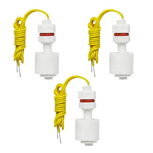
Gikfun M8 32mm Liquid Level Sensor Fish Tank Water Float Switch PP Plastic Ball Float Controller DIY Kit for Arduino EK1373x3 https://www.amazon.com/dp/B07G13JB57/ref=cm_sw_r_cp_apa_i_WNrnDbVD86S56
I get ya... just one more idea.
You could wire a 24v transformer to a float-switch - then from the float to a 24v solenoid valve. When the float is triggered it will shut off the valve.
Do you think something like this would be okay? https://www.amazon.com/dp/B07CWR234L/ref=cm_sw_r_cp_apa_FiGJBbMH1XX65
It is a glass plate on aluminum. Specifically this bed Anycubic 43188-247109 Ultra Base 3D Printer Platform with Aluminum 12V/24V Dual Power MK3 Heatbed, Tempered Glass Plate, Durable Build Surface for Prusa I3 220x220mm https://www.amazon.com/dp/B075375HBY/ref=cm_sw_r_cp_apa_q31TBb1HR4FW4 and this sensor at 12V BALITENSEN LJ18A3-8-Z/BX 8mm Approach Sensor Inductive Proximity NPN No Switch DC 6-36V https://www.amazon.com/dp/B078SF8SJ8/ref=cm_sw_r_cp_apa_.41TBbMVVGJGN no idea why it didn't work.
Will do. So far, things have been pretty straight forward. Marlin config has taken a bit, I will post the final Configuration.h and Configuration_adv.h when I'm done.
​
The biggest challenge was the Z-Probe. The logic on the endstops for the SKR is 5V, but the printrboard and probe are 12V. There was talk on the interwebs about solving the issue with a voltage divider with resistors - but that maxed out my electronics knowledge. A 5V inductive sensor was only $15 (for 2) so I bought them and it works perfectly and reliably.
https://www.amazon.com/gp/product/B073XD44CW/ref=ppx_yo_dt_b_asin_title_o02_s00?ie=UTF8&psc=1
​
I'm down to calibrating everything, and I'll do a final update once it's all done. My first print will be a board tray that can be fit up inside the metal plus underbelly. Right now, everything is wire spaghetti behind the printer.
I tried looking for a Jaguar disassembly video, but didn't have any luck. Instead, I tried searching for tilt sensors at Amazon. In addition to ones like this, which look like the ones in the older RB guitars, there were also acceleration sensor chips like this. That's a three-axis accelerometer chip, that can tell which way gravity is pointing. Maybe one of those little chips is the sensor.
THIS sensor works great for me. I had to wire it to the power supply instead of the 5 volts from the original port, but I haven't had any issues with leveling since. You will need to print a piece to hold it tho. I used something like this to attach it near the hotend.
This is my vote for sure. You can monitor the water level in the sump pit easily with a float switch. Something like this works nicely:
https://www.amazon.com/dp/B01LYCTVT1
I'm putting a pair of these in a cistern to control turning on/off the well pump. I'm also adding a second pair low and high water alarms.
I'll start with the non-printable mods:
Replaced the PSU with a 750w ATX PSU I had lying around.
If you do this, you will more than likely need to add a power resistor to the 5v rail. I also removed all the original wires and connectors from the PSU and resoldered just what I needed with better rated wire.
Glass bed on top of the aluminum. I just went to Lowes and got them to cut a few pieces of single pane glass.
Mosfet circuit for the heated bed:
https://www.amazon.com/BIQU-Power-Module-Expansion-Printer/dp/B01HEQVQAK/ref=sr_1_1?ie=UTF8&qid=1493092441&sr=8-1&keywords=3d+printer+mosfet
Upgraded Y Carriage:
https://reprapchampion.com/collections/heated-beds/products/anodized-aluminum-y-carriage-plate-upgrade-v2-for-prusa-i3-reprap-3d-printer
New Belts:
https://reprapchampion.com/collections/linear-motion/products/10-meters-6mm-width-gt2-timing-belt-for-reprap-delta-3d-printer-kossel-rostock
Geared Pulley to replace the smooth one:
https://reprapchampion.com/collections/linear-motion/products/3d-printer-idler-pulley-aluminum-dual-ball-bearing-3mm-bore-16-teeth-gt2-belt
Upgraded Heated Bed, this bed heats up slow and I also lost a little bit of build volume. I plan on getting something better here very soon. Once it's up to temp it works well though.
https://reprapchampion.com/collections/heated-beds/products/new-improved-mk3-aluminum-reprap-3d-printer-prusa-i3-heated-hot-bed-build-plate
Inductive Sensor for auto level:
https://www.amazon.com/gp/product/B01LWNCY4C/ref=oh_aui_search_detailpage?ie=UTF8&psc=1
Copper Tape Because the inductive sensor can't see glass I put this on the bottom side.
https://www.amazon.com/Tapes-Master-10ft-Copper-Foil/dp/B00Z8MCJW2/ref=sr_1_6?s=industrial&ie=UTF8&qid=1493092625&sr=1-6&keywords=copper+tape
Firmware:
To get the sensor working, you'll have to change the firmware unless you only want to use it as a limit switch. The only option that i'm aware of is Skynet which is based on Marlin and works fairly well. You can find that on their facebook page: https://www.facebook.com/skynet3ddevelopment/
Blue LED Extruder Fan (because the original broke). I don't remember where I got this from. I'd like to find an RGB one! ha
I added a bunch of WS2812 LEDs controlled by an Arduino at the moment, I am using OctoPi so eventually i'll have that control them but at this point they're set to UV colors because it looks cool.
Printed mods:
Frame braces:
http://www.thingiverse.com/thing:1857991
http://www.thingiverse.com/thing:1430727
Y Carriage Risers:
The Y carriage sits too low and will smack into the Y axis motor so I made these risers to solve that:
http://www.thingiverse.com/thing:2226564
Y Belt Clamp: You'll need one for the new carriage, but I cannot find the one that I used.
Auto level bracket: Though I only have PLA and it kept warping so I made a metal version of it:
http://www.thingiverse.com/thing:2006986
Anti-Z Wobble I modified this but no longer have the file, I also printed a cylinder to wedge into the hole above the lead screws.
http://www.thingiverse.com/thing:1858435
Bearings I used:
https://www.amazon.com/Beerings-Malt-ABEC-Skateboard-Bearings/dp/B005NFXHQG/ref=sr_1_2?ie=UTF8&qid=1493094188&sr=8-2&keywords=beerings
Belt Tentioners I can't remember which ones I finally used.
I think this is everything. If I remember something else i'll post it.
Look for a "hall effect" flow sensor to give you a measurable flow rate. Not sure what you plan to use to read the sensor, I've interfaced these with an arduino before. Something like this? https://www.amazon.com/uxcell%C2%AE-Effect-Sensor-Flowmeter-0-25-3L/dp/B01FJRA4IQ
So, if I'm understanding you correctly, you simply want position feedback, and not the ability to control motors? If so, I have had good results with these encoders. They are simple and fairly inexpensive. They are relative, which means they do not report a position inasmuch as they report a rotation. It is up to you to keep track of their rotation and to zero it out. A known position + a rotation gives you a known position, but you will have to zeroize them when you start up. this could be bad if your system crashes during a performance, you'll have to physically zero out the projectors position. so you may want to look at an absolute encoder, such as this one, which I've never used.
The other problem you will run into is that unless the encoder is mounted directly onto your shaft, you will have to use a transmission of some type (belt and pulley, gear, etc) to rotate the encoder. You will have to measure the turn ratio of shaft to encoder to ensure that the values you are getting back are accurate. For example, if there is a gear reduction of some amount, your encoder will spin fewer times than your shaft, give you bad values. Since I dont really understand where you will mount it, that may or may not be an issue.
Now, others in this thread are telling you to look into an arduino, but they do not have networking capabilities, so by the time you buy a network shield and code up a working osc/udp translation layer (there's probably a library for it, but who knows), you will have spent more time and money than if you just went with the pi, in my humble opinion. Python can run osc and python is very nice for beginners, compared to c++ which you'd be using on an arduino.
What?! We measure time of flight all the time. That's how RADAR works, and it's how all laser distance sensors work. I have a TOF laser sensor on my desk right now that costs less than $3.
https://www.amazon.com/HiLetgo-VL53L0X-Distance-Measurement-Breakout/dp/B071DW8M8V/ref=sr_1_3?keywords=TOF+arduino&qid=1566745175&s=gateway&sr=8-3