Best interfaces according to redditors
We found 158 Reddit comments discussing the best interfaces. We ranked the 88 resulting products by number of redditors who mentioned them. Here are the top 20.
We found 158 Reddit comments discussing the best interfaces. We ranked the 88 resulting products by number of redditors who mentioned them. Here are the top 20.


These are parts I use consistently in my labs
Capacitor kit
Resistor kit
Jumper wires
Bread board(s)
Larger breadboard. Recommended for larger projects but I haven’t used it too much. Best for large IC circuits
Multimeter. This has all the right features
Other things that can be useful:
•Wire strippers
•Pliers
•Electrical Tape
•Tackle Box or tool bag (to carry everything)
•Flat jumper wires
As you get into classes you’ll need specific parts (transistors, logic gates etc) but this should get you started. I use the things I linked in every lab weekly.
Feel free to message me with any questions.
Breadboard
Also a Breadboard
"A breadboard (or protoboard)"
The terms aren't as clear as you are claiming. Solderless breadboards are also called "protoboards". And solderable PCB boards with pre-drilled holes are also called "breadboards". If you want everyone to understand you, you need to be more explicit than just "breadboard" or "protoboard".
Honestly getting this was one of the best decisions I ever made:
https://www.amazon.com/AUSTOR-Lengths-Assorted-Preformed-Breadboard/dp/B07CJYSL2T
You can go pretty cheap but the absolute bottom of the barrel Aliexpress ones might have some contact issues. For peripherals it might be good to get this which gives you USB or barrel jack switching, switchable 3.3V/5V, and powers your rails. You also would want a set of prebent jumpers or jumper wire depending on whether you want board cleanliness or ease of routing, respectively.
You can buy SMD breakout boards for this purpose.
If you have a heat gun and solder paste, I would use this stuff.
You can also solder with an iron. Get it aligned as perfectly as possible, Solder 2 pads on opposite sides to tack it down, then do the rest. I would add a lot of flux like Louis Rossman and put a tiny bit of solder on the iron tip. A little goes a long way! Use a stereoscopic microscope to verify your work if you have one.
Buy a speaker. Buy a little triwing screwdriver. Buy a soldering iron and a bit of thin rosin-core solder.
It's a straightforward repair, and pretty easy as far as soldering goes, but it might make some sense to buy a small section of protoboard and some segments of wire to get used to the feel of soldering, before attacking your childhood Game Boy.
I'm an ECE that got into Raspberry Pi about a month ago. I work in microelectronics (chip design), and wanted to use it to get back into larger scale electronics hacking and to do some more hardware oriented programming and projects.
As such, I had to basically reform my electronics gadget supply at the same time since I ditched my college collection a while back when moving to a new house.
Here's some of the key things I bought to go with my Pi that I felt I needed. I'm assuming you're like me and want to work on electronics hardware (lights, switches, etc).
Beyond those basic starter components, the rest is up to your imagination and what you want to do next. In my case, I plan to drive higher current components, so I'll be using optocouples and relays eventually. And I plan to make my own PCBs to snap onto the Raspberry, so I have PCBs, headers, and soldering stuff.
If you're new to the Raspberry, there's online resources out there. I also got this book off Amazon as a starter as well, which I've been coupling with online resources.
On the Arduino side, that's my next purchase since I may find it easier to have the software and server side of one of my projects on a Pi, and the hardware interface on an Arduino. I'm just going to get an R3 board to start since I have the rest of the stuff they usually include in a starter pack listed above.
This blog did a nice writeup comparing some Arduino R3 starter kits:
https://www.pretzellogix.net/2014/10/09/three-arduino-starter-kits-compared-and-reviewed/
PCB Breadboard? (https://www.amazon.com/Solderable-BreadBoard-matches-tie-point-breadboards/dp/B0040Z6OK6). Thats how those LED graphs are meant to be used. I think that, in addition with resistor packs, would help keep the wiring fairly tidy. Check out this tutorial: https://create.arduino.cc/projecthub/ejshea/led-bar-graph-and-switch-array-8467e0
If you do more custom circuit board jobs in the future you may want to get a kit similar to this one. They are meant for breadboard applications but I found they are perfect for custom circuits made on those DIY boards.
Really?
https://www.amazon.com/60kHz-atomic-clock-radio-module/dp/B01KH3VEGS
Amazon says this one is in stock. I know there are older boards that aren't made anymore... but in anycase, I'm wondering if I even need the board (and instead can pass a lot of the processing to the ATMega)
Because the flasher works with the resistance (or impedance) of the bulb to make it flash as a certain rate. Without the correct impedance, it will flash MUCH quicker.
Your headlight is probably running on an AC circuit right now. Do you to LED, you need a full wave bridge rectifier to convert it to DC.
This little guy will do the trick. https://www.amazon.com/NTE-Electronics-NTE53016-Rectifier-Recurrent/dp/B007Z7LXVQ/ref=sr_1_3?ie=UTF8&qid=1539133809&sr=8-3&keywords=full%2Bwave%2Bbridge%2Brectifier&th=1
I actually didn't tally up the cost as that wasn't really of a concern to me, but I'll try my best to provide links to the things I bought for this. Feel free to add it up for me!
I also bought various tools, like crimpers, Dremel kit, drill, etc, but I don't consider those to be project-specific as I'll have them for the foreseeable future. Let me know if there's anything you see that you think I missed!
I'm not sure what level you're at and I'm beginner myself so I'll just go over the stuff I've been doing. Maybe this stuff is super obvious.
> an incomprehensible jumble of jumper wires
If you're not using them already, the pre-cut and pre-bent wires are awesome for keeping things tidy (eg these).
> tightly packed components
Have multiple breadboards - they're like $3-5 at Tayda. The ones that clip together are handy. Having extra real estate to spread things out is invaluable. Although having long jumper wires can introduce more oscillations and noise once you've got things working you can always make things a bit more compact.
Use the buses - the outer two rows that run the length of the board for your power and ground. Use the columns of 5 for your signal path. This way you can just run jumpers up and down for your power/ground. Or if, for example, you have a resistor going to ground you can just connect it directly to the ground bus.
If you use a certain bit of circuitry in a lot of your builds consider making it on veroboard and having it off-board. I've built standard power filtering and reverse polarity protection on vero. You could do the same with something like a voltage doubler or inverter if you're always reusing them. Although it's only a few components it's a bit less on your breadboard and saves you redoing the same thing every time you BB up a circuit.
Try and lay out things as close as they look on the schematic as possible. Ground at the bottom, voltage from the top, signal running left to right. And if you can, down to the individual components. This can be hard sometimes, especially when dealing with transistors/3+ pin devices.
If you've got an old enclosure or something lying around where you can setup your off-board stuff to keep them all tidy makes things easier too. This guide from the Beavis Audio website is a good example. There's a few layout tips in that PDF also. There's also some sample layouts that might be worth a look over for some examples on how to layout certain circuit elements.
Not necessarily related to layout but a few other things I've found:
Test constantly - audio probe and DMM/voltmeter. Grab one of those little pocket battery amps (eg this one for $20) to have on your bench if testing with your real amp is a PITA.
I keep a printed copy of the resistor colour codes on the wall in front of my bench, makes it easy to glance up and check because yeah no way I'm memorising those any time soon.
Draw the pinouts for any ICs/transistors/things with more than two pins on your schematic for quick reference.
Have a decent understanding of the circuit first and how the stages work. I like to redraw stuff in KiCad/Eagle - forces me to learn what connects where. It's a lot easier when you can look at your board and go 'oh I'm missing a resistor that should be connected to the drain' (or whatever) without having to reference your schematic for everything.
I've also found I've been more successful when I'm putting things together to say in my head "signal goes through 68k resistor to gate", "1M resistor connects from gate to ground", "220p cap from gate to ground" etc etc, rather than just going "this thing connects to that". Helps you understand the circuit better and will make you then ask yourself things like "which pin on this component is the gate?".
Like I said, I'm still learning, so if I've said anything blatantly wrong feel free to call me out, always up for getting better.
Parts list for the interested
From amazon:
[perf baord](https://www.amazon.com/gp/product/B00ARTP1J4/ref=oh_aui_detailpage_o03_s00?ie=UTF8&psc=1
) $6, or any would do really.
[Battery](https://www.amazon.com/gp/product/B01LY0W11T/ref=oh_aui_detailpage_o03_s00?ie=UTF8&psc=1
) $8
[Screen](https://www.amazon.com/gp/product/B0045IIZKU/ref=oh_aui_detailpage_o02_s00?ie=UTF8&psc=1
) $18
[buttons for x/y and shoulders](https://www.amazon.com/gp/product/B0177ALAAE/ref=oh_aui_detailpage_o00_s00?ie=UTF8&psc=1
) $6
From Ebay.
[Shell](http://www.ebay.com/itm/GBA-Nintendo-Game-Boy-Advance-Replacement-Housing-Shell-Screen-Lens-Glacier-USA-/201114796639?hash=item2ed360425f:g:0Q4AAOSwV0RXufqw
) $12
[Speaker](http://www.ebay.com/itm/361510390912?_trksid=p2060353.m2749.l2649&ssPageName=STRK%3AMEBIDX%3AIT
) $5
[USB breakout board](http://www.ebay.com/itm/381578685439?_trksid=p2060353.m2749.l2649&ssPageName=STRK%3AMEBIDX%3AIT
) $0.99
From Adafruit.
Pi $5
Jst cable $0.75
Power boost 1000c $18
Mono audio amp $4
From Radio shack.
[Headphone jack](https://www.radioshack.com/collections/connectors-adapters/products/radioshack-1-8-stereo-panel-mount-phone-jack
) $3
[Volume wheel](https://www.radioshack.com/collections/trimmers-thermistors/products/radioshack-10k-ohm-wheel-potentiometer
) $2
Components for the low pass filter as also from radioshack, about $8.
Total without shipping: $100.
Great job!
I tend to be OCD with my breadboarding. Have you ever used jumper wires like the following:
http://www.amazon.com/gp/aw/d/B00W8YFSPI
They can take a little more time to use, but can make troubleshooting so much easier.
Breadboarded circuit: http://imgur.com/gallery/ESCUL
This is a Sky Quality Meter used for measuring the light pollution and skyglow at your location. It outputs values in uW/cm^2 for the infrared
and visible specturm and your limiting magnitude in Mag/arcsec^2.
It should be mentioned that these are all Amazon Prime links with two day shipping. If you can wait longer then, you can certainly get these components for far cheaper.
Rocker switch
http://smile.amazon.com/10Pcs-Round-Button-Rocker-Switch/dp/B00AKVBEN6
10 PCS @ $2.47 = $.25
Pushbutton
http://smile.amazon.com/Momentary-Tactile-Push-Button-Switch/dp/B00974ZGPE
10 PCS @ $5.59 = $.56
TSL2591 (High range light meter)
http://smile.amazon.com/Adafruit-TSL2591-Dynamic-Digital-ADA1980/dp/B00XW2OFWW
$11.44
MSP420 Stim32 I2C 128x64 OLED display
http://smile.amazon.com/SMAKN%C2%AE-Serial-128x64-Display-Arduino/dp/B010V0I8DY
$10.80
Arduino Pro Mini 16Mhz
http://smile.amazon.com/Enhancement-ATMEGA328P-Compatible-Arduino-TE362/dp/B015MGHLNA
5 PCS @ $15.99 = $3.20
5V Voltage Regulator
http://smile.amazon.com/Addicore-Positive-Regulator-L7805CV-Antistatic/dp/B00H7KTRO6
5 PCS @ $5.95 = $1.19
Grand total $27.44
You will also need an enclosure and a battery box or some other way of connecting power to the voltage regulator. I 3D-printed my enclosure but, I'm sure you can get
them cheap. As for a battery box, I use this:
http://smile.amazon.com/WAYLLSHINE-Battery-Spring-Plastic-Holder/dp/B019XT18IQ
6 PCS @ $6.98 = $1.16
I have no idea how to price the electrical tape you're going to need in order to cover the miniature star that is the power LED on the Pro Mini.
I suppose you could just desolder it. I'm not that brave. I used a 1/2 piece of black tape and blanketed the LED. Hopefully, not that much light will leak.
You can also buy protoboards that have the holes joined just like a breadboard! They can be really handy for some circuits.
http://www.amazon.ca/gp/aw/d/B0040Z6OK6
Get one of these guys, you will most likely need one for any of your lab classes anyway. Look up some simple circuit schematics, and learn to build, it can be much fun. I like this project, and your local radioshack or other electronics place will have everything you need to get started. That chip is an LMC555, a simple 8 pin timer. Once you get in the lab you will presumably have high end multimeters, power supplies, and function generators, but it is good to have a feel for building circuits before you get there, it will put you ahead of your classmates and make your labs a breeze.
You won't be able to do much without either a breadboard or a soldering iron+solder, and in the long run, breadboarding will pay for itself (being that you are a beginner).
Good luck!
Also, continuous vote tallies are suuuper duper close to being ready to go, and I got the ADC I need to get moisture monitoring set up, sometime...
I've been looking at
this: MCP3008
and
this: Using A Joystick On The Raspberry Pi Using An MCP3008
Reckon that could work?
Empty circuit boards with pre-soldered holes are excellent for small projects. Aside from learning good soldering technique, which just takes practice, there aren't really any rules. You just use a big enough piece to hold all the parts. I tend to make a lot of fairly tiny things so I end up cutting these boards into smaller pieces with a hacksaw. Waste not want not.
One popular method for Uno is to make a shield, which is a circuit board with header pins that match those on the Arduino so it plugs right in on top.
You can also stack boards, drilling holes in a circuit board to match the Arduino mounting holes and using standoffs to attach them, and running wires between the board and the Arduino. Then screw the whole thing to the underside of a countertop or whatever.
There are also tons of plastic enclosures in all shapes and sizes, with mounting holes, edge-gripping grooves, waterproof grommets, all sorts of schemes to hold things. If you have access to a 3d printer you can design and print your own custom ones.
For the 24vac, you want a rectifier (which can be a simple diode and a small capacitor - google "half-wave rectifier" for designs) and a "buck converter"
For the 110vac, most USB chargers will work just fine for 5v output, and you can use just about any DC wall wart you might have lying around with the aforementioned buck converter.
You could also use linear regulators after the rectifier, but they are much less efficient than a buck converter.
Oh cool. Are you taking a soldering iron? Then you can make multiple 'finished' projects in that time, so get a bunch of Pro Minis (and an FTDI adapter), as well as some Nanos, and some perfboard. And small wire cutters / strippers (two tools in 1).
I like ws2812b LED strips. Maybe you can spruce up your cabin or something.
Wemos D1 mini is a good ESP8266 board if you want wifi. The HC-05 is good if you want bluetooth. NRF24l01 is a good 2.4gz radio module (make two devices communicate). MPU-6050 is a good accelerometer/gyroscope. Not sure of a GPS module.
Level shifters, you'll probably want one or two if your kit doesn't come with any.
USB power banks are pretty handy ways to power a portable project.
Install PlatformIO and get it up and running before you leave. It's way better than the Arduino IDE and makes programming easier.
You could also use an LM7805.
https://www.amazon.com/Addicore-Positive-Regulator-L7805CV-Antistatic/dp/B00H7KTRO6/ref=sr_1_cc_1?s=aps&ie=UTF8&qid=1468861711&sr=1-1-catcorr&keywords=lm7805
Awesome! Thank you! I'll have to try to find something similar. That seller has zero feedback, and shipping takes way too long from Hong Kong... : \
Would I be able to find something like that, or something like this locally at a radio shack or something?
Edit
I know the amazon link I put here is 5v, I'm also asking if they make these with 1.25-1.5V Outputs too?
I don't really wanna post the code for ethical reasons (I started with some basic Adafruit code for bluetooth and turned it into a full OS). But here's a feature list:
I used u8g2's u8x8 mode for the screen drawing, as it requires no ram.
​
Here are my parts:
Voltage regulator (takes 8.4v down to 5v)
22pF capacitors
16MHz Oscillator (required for standalone board)
DIYMall blue OLED
Knockoff Arduino Uno
Adafruit UART-Capable bluetooth module (makes sending data easier)
Spare ATMega 328 processors
Li-Ion" 9V" (8.4v) batteries (rechargeable)
Switches
9V battery clip
Soldering Kit
Elegoo prototyping PCBs
Jumper wires (makes life easier & tidier)
Elegoo Starter Kit (Comes with LEDs, resistors, and buttons)
> I'm slowly turning sections into pcb
I've been doing something similar.. I'm using prototyping PCBS:
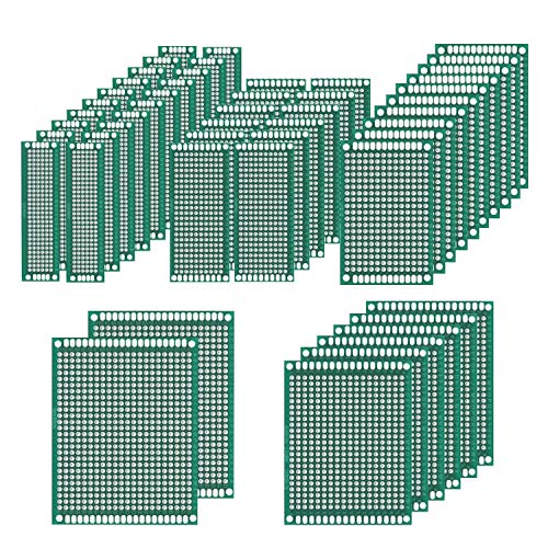
https://www.amazon.com/Prototype-Soldering-Universal-Printed-Electronic/dp/B079DN31SW
Each one is large enough to be a single component (timer, register, etc).
I thought about using wirewrap.. but decided against it because it seemed like too large a project to learn a new skill on :)
Buy some of these.
These are handy too for connecting to modules with header pins.
Don't get too hung up on making everything nice and neat, if you try to get everything tight to the board and the leads all routed straight it just makes it harder to change things.
I haven't completely drained the battery yet but I would give a safe estimate of around 4 hours. Can emulate any system up to a Nintendo 64. Does PSX, SNES, GBA, GBC, and hopefully NDS here soon.
The full parts list:
pi zero - w/ microsd card.
4.3" TFT display - https://www.amazon.com/KLAREN-Backup-Monitor-Wireless-Parking/dp/B01I58BWZK/ref=sr_1_58?ie=UTF8&qid=1486466979&sr=8-58&keywords=4.3%22+TFT
proto board - https://www.amazon.com/Mudder-Pieces-Prototype-Universal-Multiple/dp/B01ER06KXE/ref=sr_1_38?rps=1&ie=UTF8&qid=1486467094&sr=8-38&keywords=protoboard&refinements=p_85%3A2470955011
buttons - SPST-NO
adafruit powerboost 1000c - https://www.adafruit.com/products/2465
power - slide switch
the aluminum tubing for the frame was found at Lowe's in their hobby section
Lipo battery - Can use anything 1s 3.7v with the adafruit powerboost module
A few tips. Use a hotter setting, the faster you get in and out the less heat spreads through the board. But not so hot you burn out the flux. If your joint turns from shiny to grey it got too hot. I would recommend picking up these and practicing.
Good luck and have fun!
[$7.50 wire kit with $87 "expert installation".] (https://www.amazon.com/uxcell-Breadboard-Board-Jumper-Cable/dp/B00W8YFSPI/ref=sr_1_7?s=electronics&ie=UTF8&qid=1511805007&sr=1-7&keywords=jumper+wires)
It's pretty straight forward. Here are the parts I'm using:
Those are the things I bought specifically for this project. The things I already had that helped are:
This post has made me realize I have way to much electronics stuff just lying around...
My biggest issue with converting anything to LED is going from AC from the magneto to the DC that most LED setups require. On top of that, you will probably need 12 Volts since most mopeds are a 6v light circuit and that's kinda weak when it comes to LEDs.
SO, with all that in mind, you will need a 12v coil and a full wave rectifier to convert that 12VAC to 12VDC. half wave will covert 12VAC to 6VDC. If you are still going to use filament bulbs, you will also need a regulator or like 14.7v or whatever it is bulbs. Even though it's a 12V coil, it will probably shit out like 14 or so and that will blow those bulbs pretty quickly if left unregulated. LED stuff usually has a range of voltage it will accept but not always, so be sure to check that.
Anyways, this coil is cheap and already has a floating ground making the DC conversion easier.
These will work well for rectifiers (i'd put one at the tail and one at the headlight) or you could get a trail tech reg/rec if you don't mind the pricetag
I hope that makes sense.
It really depends on what you're looking to do. I realize at this point you probably don't even know what that is, but a general idea would help.
But for starters, you could get general things like:
The rest is kinda up to what you want to do, but some other suggestions would be:
These kinds of things you'd only need one to test/play with, then if you find a specific application/project, you can order more.
You can buy a kit from just about anywhere that sells electronics related stuff.
You can also buy the spools of wire or boxes and cut your own which is what the OP did. If you buy spools of wire get ~22 AWG thickness, just make sure they do not say "Stranded" or you're going to have a bad time.
Stranded wire is great for applications where you need the wire to flex or twist but horrible for breadboarding.
This maybe? http://www.amazon.com/Solderless-Flexible-Breadboard-Jumper-100pcs/dp/B005TZJ0AM/ref=sr_1_3?ie=UTF8&qid=1341350174&sr=8-3&keywords=jumper+wire ?
I've bought a pack of 70 and had lying around too and ran out on a single project! It was so frustrating having to wait for something as simple as wires to be delivered!
It's much tidier and easier than using cut cable
Just to confirm, to use a custom PCB and non-dev board, I would by something like this? https://www.amazon.com/Mudder-Pieces-Prototype-Universal-Multiple/dp/B01ER06KXE/ and would probably need a voltage regulator and some type of serial convertor to flash?
I think you'll be happy to know moving from a breadboard to a permanent circuit can be made a lot easier. I've used those individual unconnected ones before and it's pretty miserable trying to make blob shorts all day. A piece of wire helps but i start to feel like I'm making wire origami art.
What you're looking for is called a solderable breadboard there are others that move the power rails back to the outside but this helps save space.
That sounds about right. Even if it ends up not working out I would recommend you try anyway because your next project could be a success.
This will most likely also require soldering experience. I suggest you get a pack of crappy plated perf boards and a big pack of resistors and just spend an hour or two doing nothing but soldering.
The physical assembly steps could be interesting to live stream, but be careful because a lot of people will start making suggestions that may or may not be good that you would be better off ignoring.
I do stuff like this professionally, so if you have questions that aren't getting answered (or don't want to post something publicly) feel free to PM me.
Edit: Plated perf board that will work: https://www.amazon.com/dp/B072Z7Y19F
Resistor pack: https://www.amazon.com/dp/B07L851T3V
Feel free to hit me up with questions. I have always wanted to design a sex toy, so I learned a lot of relevant skills, but unfortunately I have a job that uses all of those skills now and I am too busy to work on my passion projects.
Aww, come on, give OP a break, reading is hard.
Here's a basic one you can do at home:
Here is the mobile version of your link
Using this ADC and using this sensor hooked up to a raspberry pi and breadboard with pi cobbler type attachment. Still waiting on the ADC to come in from Amazon.
Sure thing! I used a Teensy 2.0 with this code: github link. More info on using the teensy as a joystick can be found here. My code should be commented for clarity, but let me know if something doesn't make sense.
Most of the main parts came from adafruit.com or Amazon:
Assorted wires and cables came from Amazon or adafruit, make sure to find ones that are very very thin.
Using the original WiiU buttons was a nightmare. I do not recommend using the original button assemblies unless you are confident in your soldering abilities. Scrapping the original assemblies will also provide a ton of extra interior space. Connecting the 0.5mm pitch flex cable was awful, I was constantly afraid that I was going to burn through or rip something. I did actually over-solder one of the pin connectors and spent about 30 min with an iron and a needle trying to re-separate the pins. If I did this again, I would mount tact switches to a PCB and attach that to the front face of the controller. That would also save a ton of space on the inside and wouldn't require code modification.
Adafruit's Super Game Pi tutorial was also a good reference for wiring the power and audio components.
I'm happy that I could help you out with your project. Good luck and let us know how it goes!
You can buy them on an electronics store or online. Some people find these to be overpriced though, since all in all it's just a bunch of bent wires. I feel like they save me some time when breadboarding so I bought a couple of boxes a while ago.
The first item looks like a good starting point for having a small collection of components and a breadboard to test your circuits. Unfortunately if you are looking to get some practice with soldering you are missing an important piece: the actual circuit board. I also use a lot of Pin Headers in my projects, but I like to make things modular and adaptable, so the headers might not be 100% necessary for everyone.
I have a screen very similar to that, and I never use it, since most of my projects are headless, and I just SSH into my Pis remotely. But people are different, you may get a lot of use out of it.
I would also say that you don't need the anti-static mat. Not to downplay ESD, because it can certainly harm your electronics, but you would be much better served with a wrist-strap that clipped onto your computer case or something else that is grounded in your work area.
Jeg har et par af dem fra en kit.
https://www.amazon.co.uk/Adafruit-MCP3008-856-Converter-Interface/dp/B00NAY3RB2/ref=mp_s_a_1_1?imprToken=8T6MevTUTkATMIt6M60Umw&keywords=MCP3008&linkCode=g13&qid=1563247307&s=gateway&sr=8-1
I suggest getting a 9V or 6V PSU and then run that through a regulator. I use L7805CV when I need a 5V regulator. I literally just used one today to power a arduino pro mini (a 5V micro controller). I suggest using decoupling capacitors with that regulator. 10μF should do the trick. Perhaps if you gave some specifics on what you're building we could be of more help. Usually the micro controllers can power components on their own. They probably wont be able to handle 3A on the 5V pins, but you can use a relay.
Thank you for submitting to /r/SmallYTChannel. You have spent 3λ to submit here, making your current balance 2λ.
/u/PurelyStats, please comment
!givelambdato the most helpful advice you are given. Youwill be rewarded 1λ if you do so. For more information, read the FAQ.
Video data:
Field|Data
:-|:-
Title|Recreating the 40-Yard Dash Speed Test with a Raspberry Pi and Phototransistors
Thumbnail|Link
Views|111
Length|05:31
Likes/Dislikes|8/0
Comments|0
Description|In this video, we show how we created the NFL's 40-yard dash speed test that is used by scouts to evaluate the speed of potential American football prospects. To recreate the test, we used a Raspberry Pi, phototransistors, laser diodes, resistors, a analog-to-digital converter, and a simple Python stopwatch program. Using these materials, we created two laser tripwires separated by 40 yards. One tripwire starts the stopwatch, and the other stops the stopwatch. ⤶⤶For more information on the code and our wiring setup, visit our github repository: https://github.com/chris-gong/forty-yard-dash-rpi⤶⤶Thanks again to our friends for helping us out: Alex, Taylor, Ethan, Zach, and Grant⤶⤶Join our discord: https://discord.gg/2xbR5qT⤶Support us on patreon: https://www.patreon.com/flopperam⤶⤶Social media links:⤶Twitter: https://twitter.com/Flopperam⤶Instagram: https://www.instagram.com/flopperam/⤶Facebook: https://www.facebook.com/flopperam⤶Alex's Twitter: https://twitter.com/uhFakie⤶⤶Materials Used:⤶Raspberry Pi: https://www.amazon.com/ELEMENT-Element14-Raspberry-Pi-Motherboard/dp/B07BDR5PDW/ref=sr_1_4?keywords=raspberry+pi&qid=1565404835&s=gateway&sr=8-4⤶Phototransistors: https://www.amazon.com/HiLetgo-Phototransistor-Photosensitive-Sensitive-Sensors/dp/B00M1PMHO4/ref=sr_1_2?keywords=phototransistor&qid=1565404855&s=gateway&sr=8-2⤶Laser diodes: https://www.amazon.com/HiLetgo-10pcs-650nm-Diode-Laser/dp/B071FT9HSV/ref=sr_1_3?keywords=laser+diode&qid=1565404876&s=gateway&sr=8-3⤶Breadboards: https://www.amazon.com/Breadboards-Solderless-Breadboard-Distribution-Connecting/dp/B07DL13RZH/ref=sr_1_3?keywords=breadboard&qid=1565404905&s=gateway&sr=8-3⤶Battery holders: https://www.amazon.com/LAMPVPATH-Battery-Holder-Bundle-Single/dp/B07BNMKNQX/ref=sr_1_5?keywords=battery+holder&qid=1565405063&s=gateway&sr=8-5⤶Analog-to-Digital converter: https://www.amazon.com/HiLetgo-Converter-Programmable-Amplifier-Development/dp/B01DLHKMO2/ref=sr_1_3?keywords=raspberry+pi+adc&qid=1565405226&s=gateway&sr=8-3⤶Breadboard wires: https://www.amazon.com/EDGELEC-Breadboard-Optional-Assorted-Multicolored/dp/B07GD2BWPY/ref=sr_1_3?keywords=breadboard+wires&qid=1565404930&s=gateway&sr=8-3⤶10k ohm resistors: https://www.amazon.com/Projects-100EP51210K0-10k-Resistors-Pack/dp/B0185FIOTA/ref=sr_1_3?keywords=10k+ohm+resistors&qid=1565404944&s=gateway&sr=8-3⤶⤶Music Creds⤶Song: Royalty Free Music | Victory - Hip Hop Beat | No Copyright Instrumental⤶Video Link: https://www.youtube.com/watch?v=4D-LoMTbvx4⤶Music & Arrangement: Marjan Gjorgjievski⤶Mix & Mastering: Marjan Gjorgjievski⤶⤶Song: Lakey Inspired - Blossom⤶Video Link: https://www.youtube.com/watch?v=B7ArnZl_zBU⤶Follow the artist, Lakey Inspired:⤶https://www.facebook.com/LAKEYINSPIRED⤶https://soundcloud.com/lakeyinspired⤶http://instagram.com/lakeyinspired⤶⤶#nfl #40yarddash #raspberrypi
Channel Data:
Field|Data
:-|:-
Name|Flopperam
Thumbnail|Link
Subscribers|577
Videos|31
Views|54011
^/u/SmallYTChannelBot ^made ^by ^/u/jwnskanzkwk. ^PM ^for ^bug ^reports. ^For ^more ^information, ^read ^the ^FAQ.
Not sure what you bought, but this product listing is for the BB830 and it's a bit more than $3:
https://www.amazon.ca/dp/B0040Z4QN8/ref=sr_1_1?m=A2RKGEIGG4B1JT
Gotcha.
Go pick up an arduino kit, a few boards, an iron and solder.
The arduino kit will help with the physical electrical aspect, resistors, leds, servos, positive and negative, and it help with the theory/text book stuff such as amps, ohms, voltages etc.
Pick up a multimeter and look up how to test resistance , voltages, conductivity.
You can practice the soldering by putting led and resistors on a board. The arduino has tons of material for simple projects that include the code. So if the coding part doesn’t interest you, just copy the example
Code and build the circuit on the included breadboard. Then move the circuit into a blank soldering board
And make sure to research any questions instead of just asking someone who knows the answer. The reason I suggest research on your own first is there’s a lot to learn in the tech industry. The more you read the more you’ll familiarize yourself with key words, go to forums, and terminology.
I believe they mean an adapter, such as these ones:
https://www.amazon.com/dp/B07CJ96ZPW/
Wow, yeah thats super small. That looks like something that has a specific purpose. Check these out.
https://www.amazon.com/Double-Sided-Board-Prototype-Paxcoo/dp/B01N3161JP/ref=sr_1_1_sspa?ie=UTF8&qid=1522698761&sr=8-1-spons&keywords=perfboard&psc=1
EDIT: Found the problem. You searched for "Perf Board". Try "Perfboard". Here is the same thing on the DE amazon.
https://www.amazon.de/Aihasd-Lochrasterplatte-Lochrasterplatine-Leiterplatte-Universal/dp/B00VL1KHJQ/ref=sr_1_4?s=ce-de&ie=UTF8&qid=1522698858&sr=1-4&keywords=PerfBoard
amazon starter $20
proto practice boards
practice resistors
Yeah, you just need one of these guys
I've thought about building this very thing for my mom, who can't set a clock to save her life.
I figured it could have the following:
Links:
> cheap out and save a 3.3v regulator (those are expensive for some reason)
Order a handful of LD1117 from Aliexpress, you can get them for $.30/ea
They aren't even that horribly priced an Amazon with prime
Nice switches.
How many do you have to mount?
1-5: and glue them in.
6-20: buy prototyping boards , solder switches and drill holes to mount them.
20+: design a small pcb with mounting holes and have it made in china.
Neat. that said I have so many spare perf boards for making prototypes, and that's generally what I use. perf board amazon kit
Would this work? https://www.amazon.com/NTE-Electronics-NTE53016-Rectifier-Recurrent/dp/B007Z7LXVQ
The current version is on one of those solderable breadboard and it's fairly neat (i.e. four rails for power/ground and then several connected horizontal lines) such as this one: [here] (http://www.amazon.com/Solderable-BreadBoard-matches-tie-point-breadboards/dp/B0040Z6OK6/ref=sr_1_1?ie=UTF8&qid=1377062803&sr=8-1&keywords=solderable+breadboard) .
I was hoping that protoshield was just a solderable breadboard but with Arduino connections on top of it.
Snoothing caps? Is that when you put a capacitor on output, and ground of a voltage regulator? Okay thank you. A while back i bought these voltage regulators, i took a quick look at the spec image they provide, and im still new at reading that stuff but i believe max is 800mA
(12-Pcs) STMicroelectronics 3.3V 950mA, LD1117V33 Voltage Regulator, LD33V https://www.amazon.com/dp/B01N09X4E8/ref=cm_sw_r_cp_apa_i_t.WPDbPV6QP8E
And i bought these heatsinks, and idk if they were a good choice.
50 Pcs 20x15x10mm Black Aluminum Heatsink for TO-220 Transistor https://www.amazon.com/dp/B00UBUOWWG/ref=cm_sw_r_cp_apa_i_EcXPDbP21NCGM
I decided to do PWM. If I use a transistor I won't need a heat sink, right? Will I need any capacitors?
these are the parts I've found so far (Other than motion sensors, short jumper wires, and other common items)
Transistor \
Relays/ One or the other, transistors preferably
Wires
Nano Every
Breadboard(s)
Barrel Jack
Soldering Iron
Solder
Lights + Cable - Would the cable work with the barrel jack to provide power for the Nano Every and the LEDs?
Potentiometers
50 Pcs Double Sided PCB Board Prototype Kit Soldering 5 Sizes, Universal Printed Circuit Board for DIY and Electronic Project https://www.amazon.com/dp/B079DN31SW/ref=cm_sw_r_cp_apa_i_H1HXDb9ZQ02RB