Best screw terminals according to redditors
We found 49 Reddit comments discussing the best screw terminals. We ranked the 34 resulting products by number of redditors who mentioned them. Here are the top 20.
We found 49 Reddit comments discussing the best screw terminals. We ranked the 34 resulting products by number of redditors who mentioned them. Here are the top 20.


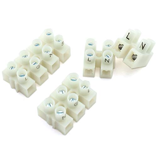


Screw terminal blocks. Used all over the world in electric installations. I much prefer these to the terrible american twist nut things.
I'm not a fan of twisting more than 4 wires. If you have a local electrical contractor supply store, get an 8-port push connector. Or, order some from Amazon.
For example: [amazon's web site] / Wago-773-168-Push-Wire-Connector/dp/B07CN6WR26/
Looks kinda like this:
https://www.mouser.com/ProductDetail/Phoenix-Contact/1862123?qs=tlR8i4ZVbUc1f5k7IsCy7A%3D%3D&gclid=Cj0KCQiAtrnuBRDXARIsABiN-7Bw9X-xP4Ks10MUICn1q7rDXfOYfPhq44Q1JzXB-dmC0GTtTntXgMIaAnElEALw_wcB
​
Can use the screw down type as well:
https://www.amazon.com/SamIdea-10Pieces-2-54mm-Terminal-Assorted/dp/B07FTJSNN7/ref=sr_1_4?keywords=terminal+block+pcb&qid=1573830689&sr=8-4
That's a screw terminal block for connecting wires without soldering.
Just don't ever jam things into the holes on your breadboard and you'll be fine. You can always solder the wire to a 0.1" spacing header pin for use in breadboards.
These are also a thing. Breadboards are spaced at 0.1" which is 2.54mm in the rest of the world:
https://www.amazon.com/Simpo-2-54mm-Terminal-150V6A-Material/dp/B07DG4798T/
Just a rough estimate. It it was around $250.
I had already had the case, 1 pid, two Switches, the Keyes switch and 3 LEDs.
Switches ($7 x2)
LEDs ($6 x4 two reds 12v and two yellows 110v)
PIDs ($24 x2)
Temperature Probes ($15)
Power Plugs ($12)
Power Plug ($19)
Element Plugs ($20)
Element Plugs ($8 x2)
Temperature Plugs ($12)
Temperature Plugs ($12)
Terminal Strips ($11)
The above list is $203.
Miscellaneous other wires, the key switch and a electrical plug for the pumps.
And I bought some new tools, including a knockout punch set from Harbor Freight.
Here’s my write up on JeepForum
This is the fuse block I used
I used 6-position covered terminal blocks similar to these, although I got them for $3/ea at a local store
This was my ground bus bar. it was cheaper when I bought it, and 10-position is nice but I probably could’ve gotten away with less
These are the waterproof sealed relays I would recommend
This is the circuit breaker I wish I used, but I had the 150A on hand. I’ll probably swap it out at some point
Edit: to add on, I used heatshrink on noninsulated female disconnects so that I could have everything properly color coordinated for easier work if I needed to make repairs/modifications in the future. I only used 1/4” Red/Yellow/Black HS on the board :)
EDIT 2: I used the wrong link for my writeup. It's fixed now!
Beauty!
Potential eventual fire hazard? Maybe.
But a beauty nevertheless!
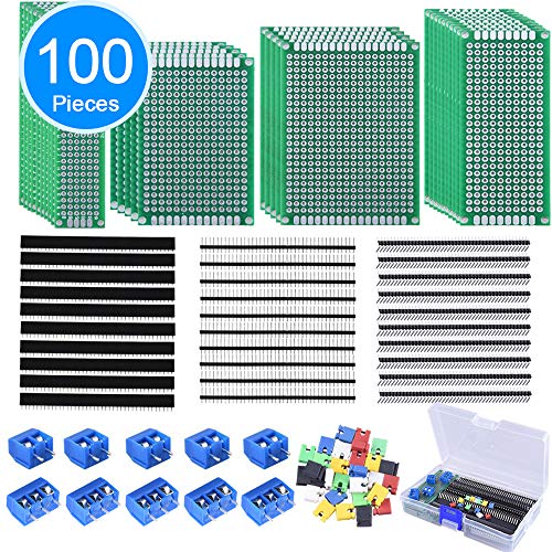
Constructive criticism: Try not to have floating resistors like the three or four near the righthand side. I understand you were running thin on both board space and lanes -- I suggest using a perfboard where the perforations are not connected, such as these:
https://www.amazon.com/AUSTOR-Including-Double-Prototype-Connector/dp/B07CK3RCKS/ref=sr_1_4?keywords=perfboard&qid=1562508877&s=gateway&sr=8-4
You can connect separate holes by bending the excess wire on your components, or, where necessary, by bridging the separated pads using solder.
An added bonus is that these also contain screw terminals which will offer a more serviceable way to connect your wires.
You will need to drill holes for mounting screws, of course, but this is doable. You can also manually cut between the rows using flush cutters if you want to cut a board that is too large down to size. This is a good way to maximize space usage.
GLHF!
It really is a neat box. I would love a wall wart that looks like that.
it's a waterprood wire nut. about 2.5" in diameter. Too small for even an average redditor.
Gardner Bender 19-2W2 Watergard Weatherproof Twist-On Wire Connectors, 22-8 AWG, Small Direct-Buried, 5 pk, Blue https://www.amazon.com/dp/B01M0HWPCW/ref=cm_sw_r_cp_apa_i_3DPLDbYTZ7Q0D
You're overthinking it:
https://www.amazon.com/gp/product/B01MFEOTSW/ref=oh_aui_detailpage_o01_s00?ie=UTF8&psc=1
This way i litterally just need 2mm of exposed wire and a phillips screw driver.
You could also use these screw terminal blocks: https://www.amazon.com/SamIdea-5-08mm-Spacing-Terminal-Arduino/dp/B07DQKSPWC I use these specifically for external power connections.
I mean, any case that can hold an mATX motherboard (and any other components, like a normal ATX power supply, GPU, etc) should be able to fit it. You'd just need to convert the non-standard power switch header to the case's standardized connectors.
The "simplest" way that I think would be relatively reliable, would be to get something like the original power connector assembly (like this one, though there are some cheaper from China, just that they'd probably take longer to arrive), cut the cables, strip the wiring just a little bit, then shove those loose wire ends into the proper corresponding normal header connections (or if you get fancy, solder them to breakaway header pin sort of things (maybe like these, though I'd have to look at actual pin sizing and make sure they're the right type)). The biggest issue with the 5-pin header on this motherboard is that the pins are much smaller and spaced closer than your normal connectors.
To adapt the sysfan fan connection to a normal fan, you'd probably need to get something like one of these or these to adapt to a normal case fan connector. Basically, you're looking for that 5-pin connector to then be able to connect it to a standard fan connector. Most people don't have spare parts lying around, but if one did have a random dell 5-pin fan, you could chop off its plug then "splice" it into a normal fan connector like this.
Don't have a picture of the flip side I'll try to grab one. It's pretty basic. I bought these fans: WINSINN 50mm Fan 12V Brushless... https://www.amazon.com/dp/B07WDG3NYZ
Clipped off the connector it came with and grouped them all together (red w/ red, black w/ black) and crimped and soldered them to these terminals:
Baomain Red Insulated Fork Spade Wire Connector Electrical Crimp Terminal 18-22AWG 100 Pack https://www.amazon.com/dp/B01B1753K2
Then connected them to a barrier strip (for easy detachment and in case I want to add another fan later):
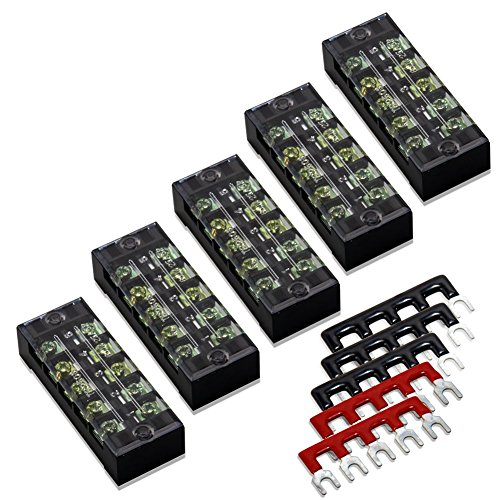
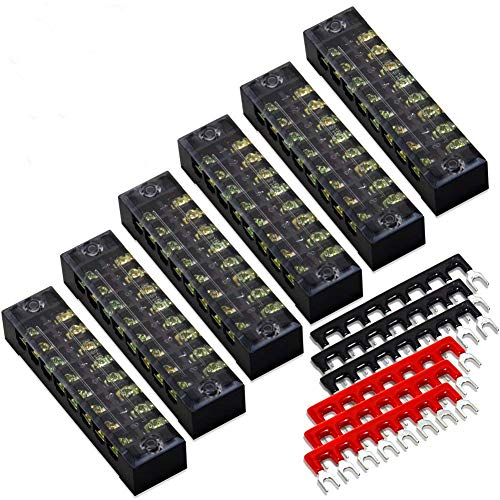
10pcs (5 Sets) 5 Positions Dual Row 600V 15A Screw Terminal Strip Blocks with Cover + 400V 15A 5 Positions Pre-Insulated Terminals Barrier Strip (Black & Red) by MILAPEAK https://www.amazon.com/dp/B07CLY91HZ
From the strip I ran 22awg wires to the +12v on the PSU.
> I would be indebted to you if you reminded us what you did and how you did it. I love creating DIY gizmos, and recall your setup being a very manageable blueprint.
I suppose we can arrange that.
---
TL;DR - 101 Ah Battery, DIY Distrubution Box w/ Banana Plugs, Mount/CCD/Arduino power cord converted to banana plug, 12V Laptop Power supply and 110V DSLR power supply hacked up, a few bits and pieces, couple of solar panels thrown in for fun.
---
The long version
===
What's important is that this be a DeepCycle or Marine battery, designed to deliver low current for extended periods of time (vs LOTS of current QUICKLY, like when starting a car) and be drained to low amounts of remaining capacity and recharged many times.
You completely do not care about "CCA" - Cold Cranking Amps. If your rig ever draws more than 10-ish Amps or so at one time, you have much bigger problems than whether your battery can deliver it. :)
What you're after is capacity, in AmpHours. I'll talk below about how to calculate your needs, if you're really wanting to be picky...but suffice to say, 50-100 Ah should be plenty for any normal AP use, especially if you'll be charging after every evening.
Mine has banana plugs on the input side, so I can plug it into my 12V power supply when I'm at home. When i'm in the field, I have some battery clips that you can plug banana plugs into like these, but you can also rig up your own if you wish with some simple 3/16" brass tubing and some solder. :)
BE VERY CAREFUL HERE The company that makes these uses black for negative, and red for positive. Great way to get confused and short your power supply, etc.
Next, read the power supply to see what its output is (or use a multimeter to find out). It is a pretty safe bet it'll be 7.4V, since that's the output of a 2-cell lithium pack, which is what most of them are these days, but check and be sure.
The, grab yourself a little step down module (You can find those in packs of 10 or more for less per piece if you think you need extras for other projects), These guys are slick....just hook up your power supply and a voltmeter, twist the little gold screw to adjust output power, and when it gets to 7.4V (or whatever your DSLR needs) you're all set.
Clip off the output cable and plug from the DSLR power adapter, solder that onto the output side of the step down module, hook up some banana plugs to the input side...done. 12V DSLR power for the night.
next to the RV. No picture, I'm too lazy to drag them out of the RV storage. heh I do want to be clear, though...having some solar recharging capacity is not necessary at all unless you're just crushing this rig for power (see below), but it IS pretty cool and gadgety if you're into such things. :)
---
Easy...you need the number of amps your rig pulls, times the number of hours you'll be using it, times the number of times you want to use it between charges, times 1.5
The two biggest consumers in a typical AP rig will be the laptop and the cooler on a CCD if you have one. DSLRs, focusers, tracking mounts, etc...None of these things use much power at all, and they use VERY little on a constant basis.
Best way to know for sure is simply to use a multimeter to measure the current each one is using under its highest load. In other words, measure the mount while it's slewing, the CCD while it's cooling, the laptop while it's screen is on and drives aren't sleeping and battery is charging, etc.
Add all those up, that's your current needs....you need to be able to provide that many amps at any given time. (That number almost CERTAINLY ought to be under 10A, hence the suggestion of a 10A fuse above).
Now...multiply that number by the number of hours you'll be running the rig. Say you pull 5A, and will be imaging for 6 hours. That's 30AH of capacity you'll use (if everything's running at max).
Now..maybe you want to be able to go camping for a weekend, and not recharge...so you want to shoot for 2 nights. Ok. 30Ah 2 = 60Ah.
And finally, give yourself a nice cushion, so you don't drain the battery completely (a deep cycle CAN handle it..but they still don't "like" it). Let's say 1.5 times the need, so 60 1.5, 90Ah.
You can quite comfortably figure on a 90Ah battery getting you two full nights of use, with no worries. :)
For what it's worth :
I run a cooled CCD, a Losmandy G11 mount, a Toshiba laptop, an Arduino-based focuser, AND support my son and I recharging our RC batteries (various 1.8Ah - 4 Ah capacity 2-6 cell packs) all off the same 101Ah battery. We can pull a complete weekend (leave on Friday afternoon, image Fri/Sat nights, fly Sat/Sun day) RC/Imaging camping trip and come home with about 20-30% capacity left in the battery. With the solar rig added on, we could go 4-5 days or more, depending on sunlight. I did my recent 3 night imaging trip with the same battery, and wasn't even down to half-empty when i got home.
Third the Wago, but think the lever nut version is a little overkill. The push wire should work.
​
https://www.amazon.com/Wago-773-168-Push-Wire-Connector/dp/B07CN6WR26/ref=sr_1_9?s=hi&ie=UTF8&qid=1541184244&sr=1-9&keywords=wago+push+wire+connector
​
All the cat5 cables ive seen have 4 pairs; blue, brown, green and orange/red and a striped counterpart. In the image posted it looks like the colors are still there, they just went with different patterns and shades.
So im seeing the orange one come out of the wall, and it LOOKS like its going into the third block from the left, but i notice its actually connected to the second from the left, so its matched with the solid orange. The fourth from the left appears to be the solid greens, as i can also see the third block contains the striped greens (as well as some of the leftover from the wall cable). And of course the far right block houses the orange striped wires. So it looks like someone was bridging the orange and green pairs, but the green striped line is broken or cut on purpose.
So like i said before if it was coming from the phone line we would only need 2 to get data to the modem, but as this is coming from a router, itll need most, if not all, of the 8 wires connected. There is a guide to wiring all this up and it goes by color of the wires, but thats just a guide and may not always be the case in how it was actually wired up.
This is how a standard ethernet cable is hooked up
Also cat 5e is just a cat5 cable that can handle more data and is better shielded so thats a non issue.
So long story short, its looks like all of them need to be hooked back up. All the suggestion in my first post should still be valid and if i were doing it i would probably run a whole new cat5 cable from the router to the pc. Failing being able to do that, i would trim up the cables in your pic, crimp new heads on following the diagram color chart, and patch them together with a female-to-female rj45 patch socket. Failing ability to do that, i would solder each wire to the other and shrink tube the joint. And lastly i would resort to twisting them together with electrical tape, or using a wire block like in your pic to join them and throw the whole thing in an enclosure like a plastic bag or something lol. Basically anything to get those wires touching and not falling apart will net some degree of success.
You'll need:
Edge trimmers
Cat5 head crimper
F2F rj45 coupler
Cat5 heads
Something similar to this 8 wire bus bar will work, but smaller would be better
And thats about it, depending on how you decide to go about the repair. Also no problem at all. shoot me another message if anything else pops up and ill help however i can.
>Can use the screw down type as well:
>
>https://www.amazon.com/SamIdea-10Pieces-2-54mm-Terminal-Assorted/dp/B07FTJSNN7/ref=sr\_1\_4?keywords=terminal+block+pcb&qid=1573830689&sr=8-4
I find these to be easier to use than the ones on the OW jigs.
That said, they may be harder to used if you have a big pot right in front.
You can use terminal blocks like these and they can be cut to however many positions you want. I've used these in many power designs over the years.
I used this https://www.amazon.com/dp/B07H53X194/ref=cm_sw_r_cp_api_i_HoxXCbND76Z1P
I was just making fun of this item earlier today but it might be perfect for your hackery.
USB 2.0 A Female Plug to 5 Pin/Way Female Bolt Screw Shield terminals Pluggable Type Adapter Connector Converter 300V 8A(2Pack) (Female)
For this job, I'd probably use some of these:
https://www.amazon.com/dp/B07CM1JQCR/ref=emc_b_5_t?th=1
 
One bar for positive (red), one for negative (black). You run a slightly larger gauge wire from your power supply to the bus bars. You then run a wire to each strip location. Just keep your polarity (red/blacks) straight. On the side w/ the bus bars, you can crimp on little spade lugs to the wires if you want it to look neat. You could mount the bus bars to a board, or put them inside a little plastic box if you want to hide it, just make sure you don't short out any of the wires if you have 'em all bunched together.
You can probably still daisy-chain a couple of those cubbies w/o too much dimming, though.
PowerSupply --> Bus ----> cubbie1 --> cubbie2 --> cubbie3
Get a "pluggable terminal block" like these (they come in different sizes, so masure which one you need), and just outfit them with any 8-35V DC power supply you have. It's meant to be flexible and DIY-ish.
manual i found: https://www.neousys-tech.com/Resource/Product_Document/Nuvo-3000/Nuvo-3000-series-User-Manual-RevA1-1.pdf
I understand tri-phase more now, thanks!
I'm using the Smartstim's Midistim design, which I haven't built yet so I'm not sure how it all works. I've read the guide and have a vague understanding. But I'm not sure what you mean by output jack or wiring harness.
If you mean the 3.5mm to 2RCA cable, I think I'll get something like this.
If you mean the resistor + terminal blocks (I assume that's where electrodes are plugged in?) I'll be getting both from Allied Electronics from the p/n listed in the Allied Electronics part list at the bottom.
Here is where I'm getting my parts unless something's wrong with it. I'm listing all in case you meant something else or want to take a look at the specs.
Both these from Amazon: Amplifier and PSU
These 5 from Allied: Resistor, Transformer, Terminal Block, BLK Patch Cord, RED Patch Cord
The rest like plate and cable ties, I'll have to find in a store (I'm not familiar with any diy but I'll get it eventually).
I also read your reply in that other thread about the quality of transformers. It seems the Allied one is the same as the Zoro one in the smartstim downloaded parts list. The quality should be good then as long as nothing goes wrong.
edit: I need to find a new source for the 1 or 2 terminal blocks, Allied require a minimum of 100... I heard the terminal blocks don't need to be exact so I can get away with a variation. I found this terminal block and it might work.
I'd clean it up with one of these and it would still fit in a regular junction box.
https://www.amazon.com/uxcell-Positions-Terminal-Electric-Barrier/dp/B01M73WTGG/ref=sr_1_6?crid=324IIXH6JK09&keywords=terminal+block+8+position&qid=1550350588&s=hi&sprefix=terminal+block+8+p%2Ctools%2C152&sr=1-6
oops, that might just be a straight through, but they make versions so everything is internally connected.
It's a silicone-filled twist-on wire connector, about 2" long so just about right for OP.
Thanks. Polaris taps and a transition j box are the missing pieces for me. Do these look right? https://www.amazon.com/NSI-INDUSTRIES-GIDDS-106850-Insulated-Connector/dp/B00CTTN7J6/ref=pd_sim_328_1?_encoding=UTF8&pd_rd_i=B00CTTN7J6&pd_rd_r=M0MGGKHG2GT7MM4KFGB8&pd_rd_w=iDRbv&pd_rd_wg=8oMXL&psc=1&refRID=M0MGGKHG2GT7MM4KFGB8#feature-bullets-btf
Ah, figured it out. https://www.amazon.com/Polaris-Insul-Tap-Connector-Splicer-Reducer/dp/B00CTTN7J6 is for 12.
The one I recomend uses mirco USB. I ended up having to re-wire everything too but lucky for me, I just had to tap into the 12v power supply from the rear view mirror. I tuck everything underneath the headliner.
I bought this
And soldered these to the bare ends. I used those pins to put them into the connector behind the rear view mirror. Looks like this.
Sure do.
Terminal Blocks
4 Conductor Wire
You can pretty much do as you wish. You can normally put 2 or more wires in those clamp down terminals.
In my day, we'd use something like this to connect up our circuit.
Agreed, check parallel vs series. Each has it's strengths. I have ramps, but still run off one 4pin interface. I cut one of these down to 4, and mounted it in the screw holes above the arduino.