(Part 2) Best electrical wires according to redditors
We found 413 Reddit comments discussing the best electrical wires. We ranked the 179 resulting products by number of redditors who mentioned them. Here are the products ranked 21-40. You can also go back to the previous section.


And here are the details of my build.
The basic circuit is:
[power brick positive] -----> [switch] --------> [Induction module] ----------> [power brick negative]
Here is the list of purchased parts I used:
The items I had laying around are a mason jar (cleaned with new lid), 18 gauge speaker wire, and ferrule crimps.
The wire is cut to length, stripped ~1/8" (3mm) at each end, a ferrule is crimped on each end, and then inserted into the screw terminal. The ferrule is not mandatory, but it provides a more secure connection that bare wires, and I think its important to include when many people on this sub do not have background working with circuits.
Amazon. I use BNTECHGO brand and have no complaints other than its expensive for 10 feet of wire. But I didn't find much cheaper really. Any silicone wire will do.
I use https://www.amazon.com/gp/product/B01CQJF3BS/ for ESC signal/all other low power wires on the quad. And https://www.amazon.com/gp/product/B00TG1TRL2/ for ESC power.
For my next signal wire purchase I might go up to 26 or 28 gauge. The 24 isn't too big at all but smaller would work just fine too.
Battery, Voltmeter, Wire, Pusher, Motors, MotorCover, Micro Switch, Charging Stuff, Charging Stuff, You're idea is pretty good, no comments on improvement.
Edit: Formatting
TBH, I buy them in those bins with the little compartments that have them all separated, then when I take them off the breadboard I toss them into a box and eventually give them to a local school...
It is just not worth my time to re-sort and organize.
Here is a link to how I buy them:
https://www.amazon.com/AUSTOR-Preformed-Breadboard-Assorted-Prototyping/dp/B07PQKNQ22/ref=sr_1_1_sspa?crid=FRG5U3910R5M&keywords=breadboard+wire+kit&qid=1558456703&s=gateway&sprefix=breadboard+wire+%2Caps%2C127&sr=8-1-spons&psc=1
I did a similar thing just a few days ago and considered writing up an instructables on how to accomplish rewiring any window/wall Ac unit. When I get back from vacation I'll put something together with pictures but for now I'll walk you through from memory.
Parts:
AC unit - in my case I started with a broken GE 10,000 BTU window unit. The fan and compressor work fine but the control board (digital) got moist and shorted out.
Thermostat - I have been using an ecobee3 in my home to run the boiler during the winter so I decided that everything would be nice if it was centralized to the ecobee.
Relays for the compressor and fan - Supco 90380 General Purpose Fan Relay, 13 A Load Current, 24 V Coil Voltage, Normally Open and Normally Closed Contacts https://www.amazon.com/dp/B004XS1ZX6/ref=cm_sw_r_cp_api_YqmuxbP3XPNTR
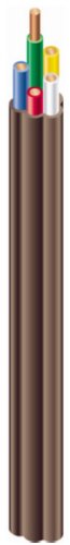
Thermostat wire - you can get this from any hardware store but I went with this from Amazon. Southwire 64170422 18/7 Solid Copper Class 2 Power-Limited Thermostat Wire, 50 feet https://www.amazon.com/dp/B0069F4HEU/ref=cm_sw_r_cp_api_hsmuxb6T3TT5N
24vac transformer - if you don't already have your thermostat wired and powered with a heating system you will need to power the relays and thermostat.
Assembly:
The control board or knobs on an AC is really just a bunch of solid state relays so what we essentially need to do is replace those relays with ones controlled by our thermostat of choice. If your unit is digital it usually will have a 12vac transformer to power both the board and provide enough power to switch on the relays. This transformer is not enough to power a smart thermostat so remove it.
Removing the control board exposes several wires, it may take some trial and error as each unit will have different colored cables but pay attention to how the control board or knobs are wired. Usually on the board it has labels like fan (low, med, high) and compressor. These are 120vac heavy duty wires that directly wire back to the compressor and capacitor of the unit.
You want to remove your desired fan speed leads and wire them to one of the "normally open" sides of the relay you purchased. You then will do the same for the compressor.
Now that you removed the guts of the AC control unit. You can wire up the thermostat to control the relays. You need 3 of the wires that are coming off your thermostat. Note that if you do not have the thermostat wired up to the heating in your home already you will need to power the thermostat with the 24vac transformer.
Assuming that you have a thermostat connected to a system already the 3 wires you need to run to your AC are a common (typically blue) a cooling signal (typically yellow) and the fan signal (typically green). The blue needs to wired to both relays and yellow/green independently to the corresponding relays.
At the end of the day you should have 1 relay dedicated for cooling and one relay for fan. Once everything is wired up plugin everthing and hope for the best. If successful when the thermostat triggers the cooling call it should flip on both relays and produce cold air when it just turns on the fan it should enable only the fan relay.
Hopefully that's enough info to get you started. I'll put something better together next week when I am back. Good luck!
That's your best bet with what's in stock.
However, if you are even slightly handy, you could put together a better, dimmable setup with this board/heatsink and this power supply. To wire it all you would need is this wire and these connectors
I actually didn't tally up the cost as that wasn't really of a concern to me, but I'll try my best to provide links to the things I bought for this. Feel free to add it up for me!
I also bought various tools, like crimpers, Dremel kit, drill, etc, but I don't consider those to be project-specific as I'll have them for the foreseeable future. Let me know if there's anything you see that you think I missed!
It was all separate. The charger cable and 50 amp wire I bought on Amazon:
https://www.amazon.com/gp/product/B077DC39J9/ref=ppx_yo_dt_b_asin_title_o00_s01?ie=UTF8&psc=1
https://www.amazon.com/gp/product/B000HEHCMS/ref=ppx_yo_dt_b_asin_title_o00_s00?ie=UTF8&psc=1
The rest is from Home Depot.
I bought this pack at my local electronics store. Not sure if it ($10) qualifies as frugal but now I'm set for a long, long time.
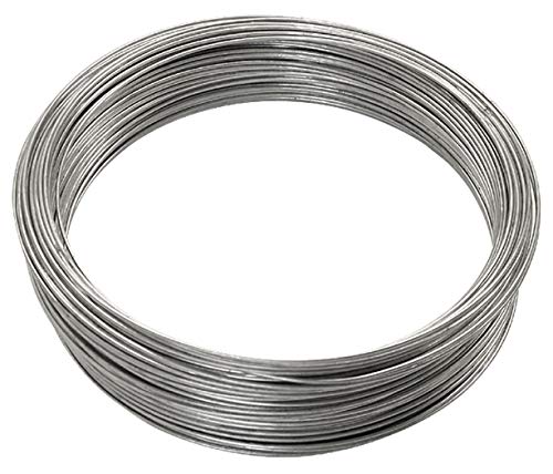
OP you need some bailing wire.
For a breadboard I prefer something like this:
https://www.amazon.com/AUSTOR-Preformed-Breadboard-Assorted-Prototyping/dp/B07PQKNQ22/ref=nav_signin?keywords=breadboard+cables&qid=1566541157&s=gateway&sr=8-8&
Hello again! Here was my shopping list (I am sure that there are better!) and I think that this was everything that I had in front of me when working:
For the Gameboy:
- screen and glass (and this came with screwdrivers but I bought others because it doesn't say that it does), https://www.ebay.co.uk/itm/10-Levels-High-Light-V2-IPS-Backlight-LCD-Screen-Kit-For-Game-Boy-Advance-GBA/312745721491?ssPageName=STRK%3AMEBIDX%3AIT&_trksid=p2057872.m2749.l2649
[one regret = I should have bought a funny playing screen to support the person that came up with this mod rather than from China directly]
- screwdrivers: https://www.amazon.co.uk/gp/product/B01KFJK7MQ/ref=ppx_yo_dt_b_asin_title_o02_s00?ie=UTF8&psc=1
- black silicone buttons (haven't arrived yet so I cleaned my original ones with a toothbrush and isopropyl alcohol for now), https://www.ebay.co.uk/itm/For-Game-Boy-GBA-Advance-Button-Silicone-Rubber-D-Pad-Conductive-AB-Select-Start/312608709452?ssPageName=STRK%3AMEBIDX%3AIT&var=611338502576&_trksid=p2057872.m2749.l2649
- black button set, https://www.ebay.co.uk/itm/Button-set-for-Game-Boy-Advance-Nintendo-GBA-custom-mod-AGB-001-Black-ZedLabz/371907958966?ssPageName=STRK%3AMEBIDX%3AIT&_trksid=p2057872.m2749.l2649
From this company I bought the following (but their website is down for maintenance now): www.deadpanrobot.co.uk/
- case that was pre-cut for a new IPS display (it is central in the glass screen now): Mandarin Shell For Nintendo Game Boy Advance
- 3D printed mount (useful but the screen came with two bits of plastic that would have done the job (see the video that I linked 'person that filmed the whole process')
- Model Sticker For Nintendo Game Boy Advance (just so it doesn't look empty on the back)
​
For soldering:
- solder, https://www.amazon.com/EL60-40-25-Electronic-Solder-Resin/dp/B0001P171K
- wires, https://www.amazon.co.uk/gp/product/B01F8PO8OA/ref=ppx_yo_dt_b_asin_title_o00_s00?ie=UTF8&psc=1
For cleaning connections:
- Isopropyl alcohol
- Cotton wool buds (Q-tips?)
Module and Coil
ZVS Driver Module,5V-12V ZVS Low... https://www.amazon.com/dp/B01CNM24YM?ref=ppx_pop_mob_ap_share
12V 20A LED switch with cover
AutoEC New 12V/20A Red LED Illuminated On/off SPST Car Automotive Toggle Switch Button https://www.amazon.com/dp/B012IHZW4G/ref=cm_sw_r_cp_apa_i_YIOWCbX59GG36
18 gauge wire
BNTECHGO 18 Gauge Silicone Wire... https://www.amazon.com/dp/B01AQOI36M?ref=ppx_pop_mob_ap_share
12v 6a power supply
AspenTek Us Plug Dc 12v Power... https://www.amazon.com/dp/B00GU63ICU?ref=ppx_pop_mob_ap_share
Then I used three spade connectors to attach the wires to the switch, which you can get from walmart
Wire ties. Not the plastic kind, actual ties made of steel wire.
Get this and this for yourself or a fellow builder for Xmas! Less than $45 should get you through the next 5 years unless you rewick multiple times per day. 1000ft of wire is enough to make 2,000 standard coils if you're cutting 6in per coil. It's time everyone stops paying a high premium for "special" wire and cotton.
i've had this problem many times.
its almost certainly that your wires are making intermittent contact. i've had to replace my bed sensor wiring and power wiring about 4 times.
once however my actual temp sensor cracked in half and i had to replace it with a 100k thermistor.
https://www.amazon.com/Gikfun-Thermistor-Temperature-Sensor-Printer/dp/B018QL5LPI/ref=sr_1_4?ie=UTF8&qid=1481397650&sr=8-4&keywords=100k+thermistor
here are the thermistors and as for the wiring, if thats what it turns out to be(most likely is)
sensor wiring
https://www.amazon.com/gp/product/B01708AYYQ/ref=oh_aui_detailpage_o05_s00?ie=UTF8&psc=1
power wiring
https://www.amazon.com/gp/product/B00TG1TRL2/ref=oh_aui_detailpage_o05_s00?ie=UTF8&psc=1
i also recommend using https://www.amazon.com/Wago-222-412-LEVER-NUTS-Conductor-Connectors/dp/B00HIOP6SC/ref=sr_1_5?ie=UTF8&qid=1481397789&sr=8-5&keywords=wago+connector
for the wiring inside the unit, so that your wiring can be replaced easily without buying a new wiring harness.
https://www.amazon.com/Wago-222-415-LEVER-NUTS-Conductor-Connectors/dp/B07CN5974J/
Or look for a terminal block and jumper the one side.
But it seems to me that this may be a bit beyond your ability to do safely, maybe play around with low voltage switching before this.
What are you talking about with positive and negative? I hope that your relays are switching the black (hot) wires and not the white (neutral) wires.
You probably don't need a 12ga feeder, the wires in the wall are probably 14ga anyways and I'm guessing that you're not switching more than a couple hundred watts of lights.
And what amperage are your relays rated for? I'm hoping at least 10 amps. I would consider fusing the incoming power at the rated load of your relays if they're rated for less than 15 amps.
Also, don't tell the insurance company about this, technically you need to get that device inspected before plugging it into the wall.
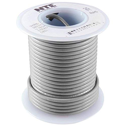
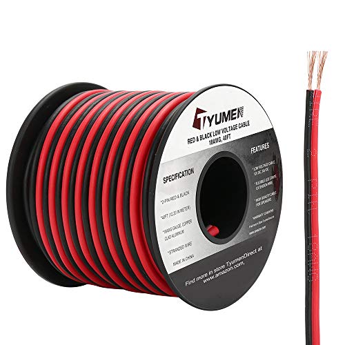
Consider investing in a box of silicone wire. You can buy an entire box of 18 AWG wire for $19 on Amazon. This wire should be good for up to 30A. It comes in multiple colors but you can also get it in just black or red/black.
https://www.amazon.ca/gp/product/B01LH1FYHO/ref=ox_sc_act_title_2?smid=ANPVYBWUHNHQ2&psc=1 "tinning" wire?
Solid core wire is your best friend. It’ll hold whatever shape it’s in.
Top once, then hold everything down with a little bend of solid core wire. Adjust weekly as it grows. Super easy.
https://www.amazon.com/dp/B001IRVDV4/ref=cm_sw_r_cp_api_TfI1Ab3Z62RJM
I was running this at 2.5 amps without a heat sink but it will take much more if you have a fan or heat sink. 18 gauge wire will do fine with some headroom (1mm if metric). 20 gauge wire would normally be fine but low voltage wire can come in a connected pair so they are derated. For example, this 20 AWG wire pair is being derated to 3.2 amps by the manufactuer although the current-wire size charts would normally show this wire to be fine. That wire would be fine for 30-35 watts on this LED and the same wire I used on my testing.
Buy this 18 AWG wire:
https://www.amazon.com/BNTECHGO-Silicone-Flexible-Strands-Stranded/dp/B01AQOI36M/ref=pd_lpo_sbs_60_t_0?_encoding=UTF8&psc=1&refRID=YPDAJMHZ4QMNAVG1TRSJ
Keep in mind that this is a constant voltage setup that you're likely doing. 12.6 volts and 12.8 volts can have a significant difference on current levels and how hot this COB gets so you want to actually measure the current level. Different COBs can have different voltage drops and COB temperature also plays a role in voltage drop and thus current levels in a constant voltage setup.
In that case, use these WAGO's.
Daisy chaining is going to be unreliable.
By the way, take the old ballasts to a recycle center, they may even give you a couple bucks for them. Better than going into a landfill.
It's nice, honestly I can't recommend it enough, especially with the v2 rda..
Pretty much any coils you want to use will work, I build my own with this and run it in single coil and yooo if you like clouds, that's him 👌
Battery life is great with 18650s but I bought 3 20700s and they were a killer investment
http://www.amazon.com/Southwire-64170422-Copper-Power-Limited-Thermostat/dp/B0069F4HEU/ref=sr_1_3?ie=UTF8&qid=1453435850&sr=8-3&keywords=thermostat+wire
Steer clear of Cerro Wire at the big box stores.
Would this wire be okay to use to DIY usb cables?
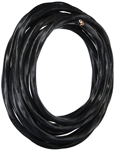
Do you have a breaker panel in the garage with two empty slots, that can handle 50 Amps? You can install a 240V NEMA 14-50 outlet for about $50 in parts, if you can DIY it. An electrician will charge you $200-300 in labor. Part of that may or may not go towards a permit. If your area requires a permit for such work and you pay an electrician, insist on seeing that permit. The heavy gauge wire is the most expensive thing if your breaker panel is far away. If you have to fish wire from a basement, it becomes an entirely different project. That heavy gauge wire is not easy to work with, in tight spaces.
I don't have a garage, so getting a weather proof outlet to my driveway from my basement was a little more expensive and tedious:
Indoors, you shouldn't need ground fault protection, so your breaker should only be about $20. Get the brand that's compatible with your panel. Without the outdoor box, a 14-50 outlet shouldn't run you more than $15. If you have a panel near by, just get the length of wire you need. If you're not fishing through the walls, you probably need to run the wire through a conduit from the panel to the outlet box. Check your local codes, or pull a permit like a good citizen. The inspector will likely be more than happy to tell you exactly what you need to do, if you ask.
The aircraft connecters:
8 pin
4 pin
10 pin (didn't end up using)
JST connectors
Wiring:
24ga silcone
16ga silicone
The aircraft connectors come in packs of 5 pairs (female/male), and I only ended up using 2 for now, but I have another printer coming that I want to enclose, so I'll probably use them there. The JST connectors you can use just crimpers to attach one end, other is soldered. I put shrink wrap tubing around all exposed metal, and in addition, I put them in the whole bundle in some nylon wrap i had laying around, but easy enough to find.
Agreed! I'm actually trying to do this right now for my setup. Does anyone know if this type of wire will work? https://www.amazon.com/gp/product/B008UFZ098/ref=ppx_yo_dt_b_asin_title_o00_s00?ie=UTF8&psc=1
-Even metric sockets/wrenches from 8-14 mm
-#2 Phillips screwdriver
-flat blade screw driver
(All above are used for removal and disassembly of the battery)
-multi-meter (for testing battery voltage and checking to make sure you're not grabbing a hot lead) You can get one super cheap at Walmart. You don't need a $100 meter for most basic multi meter usage
https://www.amazon.com/gp/aw/d/B01ISAMUA6/ref=mp_s_a_1_3?ie=UTF8&qid=1502035847&sr=8-3&pi=AC_SX236_SY340_QL65&keywords=multimeter+digital&dpPl=1&dpID=51BVqQYiV1L&ref=plSrch
-balance charger (for rebalancing the batteries)
https://www.amazon.com/gp/aw/d/B017Y2G4Y2/ref=mp_s_a_1_1?ie=UTF8&qid=1502036066&sr=8-1&pi=AC_SX236_SY340_QL65&keywords=imax+b6ac+v2&dpPl=1&dpID=51GvA3h-MNL&ref=plSrch
-18 gauge wire (I made my own wire harnesses)
https://www.amazon.com/gp/aw/d/B01LZRV0HV/ref=mp_s_a_1_8?ie=UTF8&qid=1502036364&sr=8-8&pi=AC_SX236_SY340_QL65&keywords=18+gauge+wire&dpPl=1&dpID=51CpIxqIWbL&ref=plSrch
-wire strippers
https://www.amazon.com/gp/aw/d/B000OQ21CA/ref=mp_s_a_1_2?ie=UTF8&qid=1502036896&sr=8-2&pi=AC_SX236_SY340_QL65&keywords=wire+strippers&dpPl=1&dpID=415oINm8uRL&ref=plSrch
-spade connectors
https://www.amazon.com/gp/aw/d/B01B1753K2/ref=mp_s_a_1_5?ie=UTF8&qid=1502036854&sr=8-5&pi=AC_SX236_SY340_QL65&keywords=red+spade+connector&dpPl=1&dpID=31HVegxklVL&ref=plSrch
-banana plugs
https://www.amazon.com/gp/aw/d/B00APVQZ8U/ref=mp_s_a_1_13?ie=UTF8&qid=1502036751&sr=8-13&pi=AC_SX236_SY340_QL65&keywords=banana+plugs
> Which strips exactly did you use?
These ones. Make sure to use the 60 LED/meter ones!
> Did you glue them on?
The strips have adhesive. You can glue them on or use electrical tape. Up to you. I used hot glue because it let me angle the strips slightly outwards, so more light would escape (as opposed to just shining down on the aluminum backplate).
If you want to angle the strips outwards but don't have hot glue, cut a piece of wire and use it as a fulcrum when you tape the strips down.
> Will using a 2.0 usb just not make the keyboard work or will it burn my computer my keyboard and maybe my house ?
If you're powering the keyboard of a very cheaply-designed USB hub, it might draw too much current through the device and brick it. This has an extremely small chance of happening, though. There shouldn't be any risk of fires.
I've used the keyboard on plenty of USB 2.0 hubs without problem.
> How tf do you do step one in your tutorial?
I soldered small-gauge wires - you can see them in my picture. I found silicone-insulated wire easiest to work with.
> are the strips heavy or light?
The strips feel quite light. They certainly shouldn't be so heavy as to pull the PCB down. The strips are only $10 so give it a shot and see what you think.
> How sturdy are the switches on holtites, btw?
They stopped working after some time. I'd recommend putting the Holtites in the socket instead of on the switch. I haven't had a problem with any of my switches after I did that.
Sorry for the late response!
I have some Silvania strips. I need to run 5 conductor wire across my room through the ceiling to another set of cabinet. What wire / connectors would you recommend to connect 2 sets of strips in such a configuration with a single controller?
This is the wire I found: https://www.amazon.com/dp/B0154H7BLE/
How can I easily connect this to the Silvania strips with the 5 pin ends?
I'd recommend not using Ethernet cable to wire up the thermostat. You should run a new bundle that is rated, and proper gauge for the thermostat. You'd be looking at something like this.
https://www.amazon.com/Southwire-64170422-Copper-Power-Limited-Thermostat/dp/B0069F4HEU/ref=sr_1_3?s=lamps-light&ie=UTF8&qid=1510755398&sr=1-3&refinements=p_n_feature_two_browse-bin%3A6426167011&dpID=21YbykkCq9L&preST=_SY300_QL70_&dpSrc=srch
No ragrets for $30
https://www.amazon.com/dp/B072NDD38N/ref=cm_sw_r_cp_apip_zOQawjYynBMjR
Nope. "Stranded or Solid: Stranded"
You need solid.
https://www.amazon.ca/NTE-Electronics-WHS18-08-25-Solid-Length/dp/B008UFZ098/ref=mp_s_a_1_1
Most amplifiers will tolerate a 3-ohm load, though it's possible you will get extra distortion at high volume. 18 gauge wire will be fine. As a matter of fact, if you use this whole 20-ft roll, the wire resistance will add about an extra ohm of resistance and the amplifier will see 4 ohms.
Good luck!
Save your money buying resistance wire from a vape shop. You can get 1000 feet for $20 on prime. https://www.amazon.com/dp/B01GAL3QQW/ref=cm_sw_r_cp_api_uwE3AbTJX86BY
I bought an 8 pack of grounding wires from Home Depot. I can't find the exact one I bought, but it's basically this. I'd shop around, the linked ones were not the cheapest. I had to buy alligator clips separately. Any thicker gauge wire works, but these ones already had fasteners on them. I just had to drill a hole in the wood, and then drive them in.
you can buy a bag of ground screws with pig tails already attached to them. bag of 50 is about 20$.https://www.amazon.com/Grounding-Pigtails-Ground-Screws-Pack/dp/B00CDVJA0A/ref=sr_1_2?ie=UTF8&qid=1495112568&sr=8-2&keywords=ground+wire+pigtail
put those in the metal boxes. Most metal boxes already have screw holes in the back of them for a 10-24 screw but some do not. If yours do not buy one of the drill and tap bits made by Greenlee https://www.amazon.com/Greenlee-DTAP10-24-Combination-Drill-10-24NC/dp/B000FCGRWI/ref=sr_1_7?ie=UTF8&qid=1495112488&sr=8-7&keywords=drill+and+tap+bit
you will need a bit holder for the drill to extend it deep enough into the box. https://www.amazon.com/Tonsiki-Screwdriver-Holder-Extension-Handheld/dp/B018702HQ4/ref=sr_1_6?ie=UTF8&qid=1495112723&sr=8-6&keywords=bit+extension
something like that, you will want a locking one so you can pull the bit back out.
the drill bit/tap can be a bit finicky; you go from high speed drilling to tapping in a second and if you push to hard or don't slow down, you can break the tap in half. Go slow and be prepared for it to change. Hopefully the bit wont go all the way through the back of wall. most of the time it wont because metal boxes are mostly shallow and have room inside the wall for the bit.
GFCI's do not work well without a ground and neutral. without seeing the actual wiring in person, I cannot tell you how to fix that. Do all the receptacles read as having a continuous ground? Maybe use a gfci breaker instead of receptacle?
that battery tray you linked doesnt seem to be wired up. maybe this is more what you're looking for?
https://www.amazon.com/Sackorange-Battery-Storage-Plastic-1x18650/dp/B071JBRYF3/ref=sr_1_2?keywords=18650+battery+tray&qid=1551039435&s=gateway&sr=8-2
instead of a 12" tube i'd buy something flat that you can just curl up and insert into the cylinder.
the cooling fans just look like PC case fans. almost every PC guy would recommend Noctua fans for cooling a PC, here's a nice small 80mm that i think would work well, and a controller
https://www.amazon.com/Noctua-NF-A8-FLX-Premium-Computer/dp/B00NEMG9K6/ref=sr_1_2_sspa?keywords=pc+80mm+fan&qid=1551039869&s=gateway&sr=8-2-spons&psc=1&smid=A1Z5H6ZGWCMTNX
https://www.amazon.com/Noctua-NA-FC1-4-pin-PWM-Controller/dp/B072M2HKSN/ref=sr_1_4?keywords=pc+case+fan+controller&qid=1551039926&s=gateway&sr=8-4
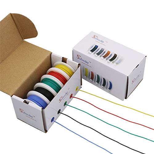
and i did find some aparently suitable wire, in multiple colors so you can coordinate your color rails.
https://www.amazon.com/StrivedayTMFlexible-Silicone-Electric-electronic-electrics/dp/B01LH1G2IE/ref=sr_1_fkmr0_2?keywords=silicon+allterm+wire&qid=1551039773&s=gateway&sr=8-2-fkmr0
​
Probably this cable installed in basement: Romex 63950021 25 ft. 6/3 Black Stranded CU SIMpull NM-B Wire https://www.amazon.ca/dp/B000HEHCMS/ref=cm_sw_r_cp_apa_i_1zcWDb6R8AK0B
Something like this?
This has happened to me too, and I think I have a wire break now that is making my machine reset during some prints. I couldn't find what gauge wire people were using though.
I know there's a video out there on how to redo the wires, but any tips for someone that is completely new to this? I've never soldered before, but have the gear for it now...just hesitating in fear of doing lasting damage.
white cable ends for steppers and the connections to the main board
https://smile.amazon.com/gp/product/B07CTH46S7
​
crimp tool for the above
https://smile.amazon.com/gp/product/B01N1RFZZ4
​
wire for the end stops and steppers
https://smile.amazon.com/gp/product/B07FMD8LFY
​
wire for the hot end
https://smile.amazon.com/gp/product/B0154H7BLE/
​
wire for the heated bed (you can go to 12awg or larger if you want -- the bead is 220w at 24v means it pulls 9 amps... as chassis wiring this should be good to about 22amps, creality used 16awg originally)
https://smile.amazon.com/BNTECHGO-Silicone-Flexible-Strands-Stranded/dp/B017TFR6SM
​
ferrule kit for the wires that go into the screw terminals
https://smile.amazon.com/gp/product/B07K17VDF2
​
I use this for the arduino and other projects -- the pin pitch is the same as the JST, but they aren't keyed or locked
https://smile.amazon.com/gp/product/B07CVYPDGS/
I figured I should add an update to this as I kinda went silent. I tried to make myself some tiger coils the day after this issue and they were consistently giving the correct resistance in the same RDA, so that rules out the RDA. I wanted to see if maybe it was because of the range of ohms I was shooting for with the coils (~0.2-0.3), so I made some triple fused claptons that should have ohmed out to ~0.1, and they were again having the inconsistent resistance ratings of between 0.1 and 1.8 ohms, which the meter would jump somewhere between every few seconds. I was frustrated at that point that all of my labor going into these coils had no worth, so I decided to ask one of my roomates if I could use two coils of theirs which were pre-built (two Stapled coils where the pair ohmed out to ~0.2 from Coilology). Turns out they are working flawlessly when it comes to reading their resistance. So I'm simply put: stumped.
I'm trying to figure out what the issue may be. I'm suspecting it must either be the wire I'm using for the claptoning (all of my wire is from this, but I know the lower awg wire is fine because the tiger coild I made from it worked!) or I am somehow claptoning my wires too loosely (which I feel is unlikely because I put a good bit of pressure on the wire which leads out of my spool, and my claptoning spacing is always so tight that I doubt this is the issue).
One thing I did notice when replacing my wires the last time was that there was a little bit of the claptoning from the end of one coil leg stuck in one of my posts, maybe I'm not cleanly cutting the legs of my coils and that's causing some claptoning to come off in the post? This makes little sense since I've used both postless and post decks with the same issue. On top of that, a little piece of wire attached to only on post would have no potential difference across it, and consequentially no current running through it during the resistance check or firing, but I'm truly pulling at straws as to why I'm having this issue. Maybe the higher awg wire from that company sucks while the lower doesn't, questions... questions...
The most DIY thing is regular paper clips. You could also visit a hardware store and buy a roll of metal wire, they usually have them in different diameters. Just look for the one you need, the one I linked is just to show you what it looks like. But with one roll of those you'll probably have all the wire you need for the rest of your life.
It's quite crazy... The core is a 3x28 wrapped in 38+2x28+2xflat(0.1mmx0.3mm) all wrapped in 38 again! The wire is on Amazon, not sure if links are allowed https://www.amazon.com/dp/B078PDTX1L/ref=cm_sw_r_cp_apa_i_UkIQDbP0H5WSH I only wish it was kanthal a1 instead of ni80. And I totally agree I had 22g round wire and it was still great from the Skyfall. :)
Edit: wow sorry for all those posts! I kept pressing post and it said try again later or something. think it got confused trying to switch to my works wifi.
These are the pigtails you’re looking for.
We always called them stingers, but you screw it down to bond to the box.