(Part 2) Best passive components according to redditors
We found 562 Reddit comments discussing the best passive components. We ranked the 286 resulting products by number of redditors who mentioned them. Here are the products ranked 21-40. You can also go back to the previous section.


Resistors are REALLY inexpensive. Throw them away and order new ones.
https://www.amazon.com/Ictouch-300value-2800pcs-Resistor-KIT0148/dp/B01NCKQCYU/ref=sr_1_fkmr0_1?keywords=Ictouch+300value+2800pcs+1%2F4W%2C+1%2F2W%2C+1W%2C+2W%2C+3W+Carbon+Metal+Film+Resistor+%2B%2F-1%25+Box+Kit+KIT0148&qid=1569975286&s=gateway&sr=8-1-fkmr0
$38.37 (considering you have a soldering iron) and don't mind doing some coding, I'd estimate it would take 20 minutes at most if your not putting much detail into it.
Library: https://www.arduino.cc/reference/en/language/functions/usb/keyboard/
Here's a Youtube video as well, https://www.youtube.com/watch?v=SHIcliL4O14
If the operator is a licensed ham and his station is in good operating order, there's not much you can do. All of your electronics have those labels on them stating that they are FCC Part 15 compliant - this means they must not create interference to a licensed device, and must accept interference form a licensed device. The law actually protects him, not the other way around.
There are ways to reduce the interference accepted by devices. Ferrite chokes are a common place to start. Wrap the leads on your speakers a few times through snap on ferrite cores (like these ). You'll also want to wrap a zip tie around the core, they snap on parts will loosen over time and the tiniest, tiniest gap renders them ineffective.
I have a link bomb of RFI prevention, along with some grounding things. That might have some helpful information for you. It generally comes down to applying lots of the proper ferrite all over.
The ham might be willing to help you correct the issue if you approach him cordially. Just nicely explain the situation. We may also be able to help some here.
Yep, that's the jist of it.
(And you'd have to cut off the connectors since the board has screw terminals)
Honestly, the hardest part is calibrating the transformers with the board. You need something to measure against, like a hair dryer and a kill-a-watt. Then there's some math and changing some values in the main program. After some time I will probably have some baseline calibrations for various CTs.
https://www.amazon.com/Ferrite-Noise-Filter-Cable-3-5mm/dp/B01N0AV746/
Put one of these on each end of your USB and speaker wires. Your wiring is acting like an antenna and picking up his transmission. Ferrite beads/chokes will help filter that out.
Yes. With shipping it's $172. And you will probably want a US power adapter.
Still worth it. It's tiny but well spaced and usable. I've had an original bassbot and x0xb0x and would take this over them any day. Pots a bit flimsy but otherwise still built better than many others twice as expensive. I think I prefer it without the sequencer- less space and I have an engine that can work like a 303 seq.
Was considering saving for an avalon but I really don't like 303 sounds that much so this is a good way to get it without taking up space/$. Most of the analog 303 clones sound good enough to me so no complaints about sound.
you can mod them too: https://www.youtube.com/watch?v=GSebDXf9rP4
I spent a good while in /r/vive before receiving my Vive. One of the suggestions that was made regarding the lighthouses and jitter was ferrite beads.
I am in a metropolitan area, but more importantly my subwoofer used to play what sounded like a radio station when it was not being used by my receiver. This lead me to believe that ferrite beads were a good investment for my lighthouses(to mitigate interference there). I bought this pack -
Ferrite Beads
I used about 4 of the ferrite beads on the subwoofer and it is no longer audible when the receiver isn't using it. I placed two ferrite beads on the power cords for each Lighthouse and have had nothing but good experiences with my Vive. Although I haven't tried without the beads, I experience no jitter.
I wouldn't have given this suggestion much thought if it wasn't for the fact that a Valve engineer actually responded and seemed to agree that RF can interfere with the lighthouses.
This is the thread I am referring to -
https://www.reddit.com/r/Vive/comments/4ghqyc/strong_rf_pollution_from_a_radio_tower_might/
Welcome! The brains of the operation is a Raspberry Pi. Connected to the Raspberry Pi are a bevy of sensors: Moisture, Temp/Humidity, Sunlight
They get checked every 10 mins and stored in a postgres db on AWS
Amazon has these.
https://www.amazon.com/PowerWell-Capacitor-TP-CAP-35-Condenser-Conditioner/dp/B01F7P8GJO/ref=mp_s_a_1_2?ie=UTF8&qid=1524946720&sr=8-2&pi=AC_SX236_SY340_QL65&keywords=35+5+440v+capacitor&dpPl=1&dpID=51MTzgfISOL&ref=plSrch
Note for the future: Please shorten your shopping links (or use reddit's feature to hide them like this). You can trim about two thirds of the URL:
https://www.amazon.com/Ictouch-300value-2800pcs-Resistor-KIT0148/dp/B01NCKQCYU
10 cents for a resistor?!
more like 50x for 10 cents.
https://www.amazon.com/MCIGICM-Resistor-Assorted-1ohm-10M-36valuesX20pcs/dp/B06XCNK5XX?ref_=fsclp_pl_dp_1
thats something close for a penny each. what does the electronics giant Sony pay?
He said his were 6Ω speakers. He was thinking of getting 2Ω resistors.
I'm a little out of the loop, but I thought 2Ω speakers were more prominent in car audio.
Anyway, assuming a 24V audio signal;
8Ω speakers = 3A draw = 72W per speaker max
6Ω speakers = 4A draw = 96W per speaker max
He's running at around 130% of max rated output on that channel, before we even get to adding in the center and the satellites.
That's all just napkin math, so it's not precise.
-----
OP, you only got so many choices here:
u/midwayfair mostly beat me to it.
You can get an assortment of topmany film box caps that will cover most of your foreseeable future needs for $15 from Smallbear.
You can also get an assortment of electrolytic caps from smallbear for $10.
[You can get a huge set of metal resistors with almost every value you'll ever need here for $10, marked with their value which is nice for initial sorting.]
(https://www.amazon.com/dp/B01J5M2G9Q?psc=1)
Wiring in parallel or series you can get to almost any value you'll need with those three purchases for $35. Not bad, right?
As for transistors/diodes/IC's, that's much more dependent on what you're building. A good rule of thumb there is every time you need 1, order 5. You'll have a nice selection (and empty wallet) in no time. Most would agree that Smallbear is the place to source those kind of "specialty" parts to make sure you get high quality/official/tested stuff. Mammoth is my personal second favorite. Tayda would be third, great prices but I've gotten some weird less-than-official looking stuff from them that doesn't always sound the same as their Smallbear counterpart.
Breadboards are for mocking up circuits.
https://www.adafruit.com/product/64?gclid=CjwKCAiA5qTfBRAoEiwAwQy-6Vh20yG6Pu3X7QUsvZ3IUAR2MR5EhKdlEPpA5rnXI_-nlAqat56QShoCZx8QAvD_BwE
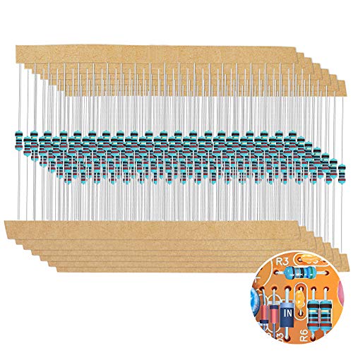
Resistors are just components but you use them all the time so it's good to have a supply of them.
Top-cofrLD 1/4w Resistors Pack 164 values x 10pcs = 1640pcs 0-22M Metal Film Full range resistors Assortment Kits https://www.amazon.com/dp/B00WE1FQ8Y/ref=cm_sw_r_cp_apa_D6t6BbSSEQQKV
DisplayPort cables are extremely sensitive to EMF, and switching a light on and off causes a spike. If the cable isn't well shielded enough, this can happen. Try picking up a ferrite ring (you don't need 15, and these might not be the right diameter for your cable, but something like: https://www.amazon.com/Bluecell-Magnetic-Ferrite-Suppressor-diameter/dp/B00MFCD56C ) and clamping it onto the DP cable and see if that helps.
I have a bunch of these on hand from some other projects... will they work as well?
It's not normal speaker wire, I'm using these (supposedly shielded) instrument cables, running to powered studio monitors. Will that work with the ferrite rods?
> Unfortunately the biggest issue is the Bose sound system runs on a 2ohm Independence for their speakers making an aftermarket upgrade next to impossible.
no so! My Infiniti is all Bose and is the same way. If the stereo doesn't see a 2ohm load when I start the car, it errors out. Just wire in a 2 ohm resistor before your line output converter, then the amp will always see a 2ohm load regardless.
I used this:
https://www.amazon.com/Chassis-Mounted-Aluminum-Wirewound-Resistor/dp/B008MLKDN8/ref=sr_1_6?ie=UTF8&qid=1503073409&sr=8-6&keywords=2ohm+resistor
and the the usual hi/lo line output converter. In my case I ran it to a Zapco monoblock and a JL sub, but you can use whatever.
Here's the explanation from AudioControl
http://www.audiocontrol.com/knowledge-base/everything-hooked-powered-music-playing-no-audio/
Now if you are trying to run component speakers, just get the 4 ohm speaker, and wire in a 4 ohm resistor in parallel. Some companies even do it on the speaker itself, so you just take a 4 ohm resistor, and connect the positive to positive, negative to negative, on the speaker terminals, then connect your wire as usual. The resistors are like 25 cents, and the amp will see a 2ohm load and you c an use whatever speakers you want.
I see this happen with my quads when I get voltage spikes. The caps should get rid of that.
6 pcs Panasonic FM Series Capacitors - 25V 470uf Ultra Low ESR https://www.amazon.com/dp/B073YQ8N55/ref=cm_sw_r_cp_apa_i_SpNRDbYWJ43E8
Something like this. You can solder it right onto the battery lead. A friend of mine gets a cap holder from brain 3d and it holds it next to the xt60. I've put leads on mine and ran it under the arm or somewhere convenient for the frame.
Yes those will work fine, but you can use a much cheaper tool for the screwdriver, they make little plastic ones called tweakers designed just for rotating small pots.
Something similar to this:
https://www.amazon.com/Potentiometer-Tools-Hardware-ADJUST-piece/dp/B00DWI1LUA/ref=sr_1_fkmr0_3?ie=UTF8&qid=1494247175&sr=8-3-fkmr0&keywords=plastic+potentiometer+screwdriver
I'd remove that stupid metal clip on it before use, but anything similar to that will be perfect.
Jameco Reliapro ACU120100D0531 AC to AC Wall Adapter Transformer 12V @ 1000 mA Straight 2.5 mm Female Plug, Black https://www.amazon.com/dp/B00B8861T2/ref=cm_sw_r_cp_api_i_51v3DbGAW1DGG
This is an AC to AC adapter, but can’t guarantee the plug fit. You may need to do some surgery. If you aren’t comfortable doing that, I’ll keep looking for more of a “universal” option.
If you had the original and could post a photo of the label, it’d help a lot.
You have to solder a resistor to the R14 jumper on the back of the pcb. I used a 100 ohm size 0603 resistor from this pack and these leds from Adafruit.
Picture of the jumpers
anything anti static should be good
https://www.amazon.com/Potentiometer-Tools-Hardware-ADJUST-piece/dp/B00DWI1LUA/
https://www.amazon.com/VISHAY-SPECTROL-008T000-ADJUSTMENT-TRIMMERS/dp/B00HKJ90V4/
https://www.amazon.com/Aven-13016-Piece-Anti-Static-Alignment/dp/B001Q4YGQS/
If you do not have doorbell chimes, you must use a resistor to simulate the wiring that would be in the mechanical chime. And you'd need a resistor on one of the wires for each doorbell. Also, running two of them off a tiny 10VA transformer probably won't work very well. It may, but you may have problems with slow/no charging also. But the resistor not being there will prevent it from charging entirely. Also, don't press the button or it could fry the other Ring since they're both attached without the resistors.
https://www.amazon.com/Cutequeen-Aluminum-Wirewound-Chassis-Resistor/dp/B06XQWJ4JP/
That's a 2-pack of compatible resistors. Since you're operating two in parallel off one transformer, you'll want to picture the wire nuts as your connection to the transformer, as it relates to the image on Ring's site. So the resistor will go on the red wire between the wire nut and the station wire, not between the wire nut and the transformer.
So I literally had to do the same thing to my MTN Dew with the same three caps. For caps, I used these. what I did was used a solder sucker, my iron and flux to remove what solder I could from the cap legs and removed the caps. Then just plopped in the replacement caps, cut down their legs and soldered them back.
My strategy was to remove what solder I could, but not focus on removing all of it as that was difficult. Just remove what you can and heat up the solder as needed when playing the new caps in.
If you need any assistance with the project, let me know and I'll do what I can.
This.. I have really been enjoying look mum's cem 3340 tutorial:
https://www.lookmumnocomputer.com/cem-3340-diy-simple/
I would strongly suggest getting a resistor and capacitor kit off ebay or amazon.. They're like 15$-20$ each. That will get you a few of a huge range of resistors and caps:
https://www.amazon.com/Top-cofrLD-Resistors-1640pcs-resistors-Assortment/dp/B00WE1FQ8Y/ref=sr_1_14?s=industrial&ie=UTF8&qid=1541720878&sr=1-14&keywords=resistor+book
https://www.amazon.com/Joe-Knows-Electronics-Value-Capacitor/dp/B007SVHFXO/ref=sr_1_5?s=industrial&ie=UTF8&qid=1541720924&sr=1-5&keywords=capacitor+kit&dpID=41%252BFAHpNRVL&preST=_SX342_QL70_&dpSrc=srch
The worst part of these projects is waiting for parts. So Building up a little surplus of this kind of stuff will make your wait time much lower..
Actually, I was an idiot. Just search for "9V transformer" rather than "power adapter," that cuts through a lot of the noise. First hit on Amazon:
Jameco Reliapro ADU090150A2231 AC to AC Wall Adapter Transformer 9V @ 1500 mA Straight 2.5 mm Female Plug, Black
https://www.amazon.com/dp/B00B886CWS/ref=cm_sw_r_cp_api_AGJxzbCCEAR3S
There are more. Now just have to find the right tip and current rating.
I did it.My transformer is shared with my upstairs neighbors so I had to reroute the wiring. It was actually very straightforward. This is the exact one I bought.
https://www.amazon.com/dp/B06XQWJ4JP/ref=cm_sw_r_sms_c_api_i_hgFXCbM0CQPC4
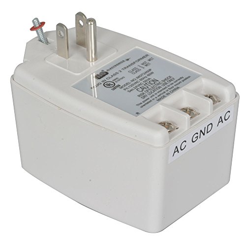
Input ( from the wall ) is 120v A/C (typical main voltage in North America) @200ma (mili amps) ( your typical plug at home give you 15 amps, 15,000 ma)
Out put ( to the device ) is 12v A/C. Requiring 1000 ma, or 1 amp.
Your adapter is a step down transformer, transforming the voltage down and the amperage up.
What your looking for is a 120v ac- 12v ac adapter
This should be sufficient
https://www.amazon.com/gp/aw/d/B00B8861T2/ref=mp_s_a_1_13?ie=UTF8&qid=1509949245&sr=8-13&pi=AC_SX236_SY340_QL65&keywords=120vac+to+12v+ac
It is a good idea to do that with resistors. Here isa nice super cheap pack that will have most of the values you'll ever need for pedal building. They are perfectly fine resistors that will fit any builds of yours. I measured several ones and they were OK.
I would not recommend it for capacitors though because this kind of packs are usually (really) low quality parts. Can be nice for prototyping though.
That sounds about right. Even if it ends up not working out I would recommend you try anyway because your next project could be a success.
This will most likely also require soldering experience. I suggest you get a pack of crappy plated perf boards and a big pack of resistors and just spend an hour or two doing nothing but soldering.
The physical assembly steps could be interesting to live stream, but be careful because a lot of people will start making suggestions that may or may not be good that you would be better off ignoring.
I do stuff like this professionally, so if you have questions that aren't getting answered (or don't want to post something publicly) feel free to PM me.
Edit: Plated perf board that will work: https://www.amazon.com/dp/B072Z7Y19F
Resistor pack: https://www.amazon.com/dp/B07L851T3V
Feel free to hit me up with questions. I have always wanted to design a sex toy, so I learned a lot of relevant skills, but unfortunately I have a job that uses all of those skills now and I am too busy to work on my passion projects.
I just realized the resistors I'm using are "metal film". I'm using these.
Here is a link to the manual.
I connected the resisters across the BNC connector using this
I appreciate your help.
I just replaced those exact caps with these: https://www.amazon.com/gp/aw/d/B072SSR65V?psc=1&ref=yo_pop_mb_pd_title
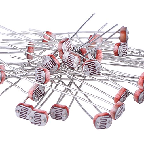
Here’s a listing of all the included material
eBoot 30 Pieces Photoresistor Photo Light Sensitive Resistor Light Dependent Resistor 5 mm GM5539 5539 https://www.amazon.com/dp/B01N7V536K/ref=cm_sw_r_cp_api_i_-wV6CbC6051BJ
Beadalon Artistic Wire 30-Gauge Bare Copper Wire, 30-Yards https://www.amazon.com/dp/B0048927RI/ref=cm_sw_r_cp_api_i_vEV6CbC9KF2ZQ
MCIGICM 200pcs 2n3904 npn Transistor, 2n3904 Bipolar (BJT) Transistors NPN 40V 200mA 300MHz 625mW TO-92-3 https://www.amazon.com/dp/B06XRBLKDR/ref=cm_sw_r_cp_api_i_UEV6Cb66Z0SC2
3mm Diffused LED Diode Assortment Kit - Pack of Assorted Color LEDs and Resistors (1000 pcs) - Red, Green, Yellow, Blue and White Light Emiting Diode Indicator Lights from Plusivo https://www.amazon.com/dp/B07GBFJ823/ref=cm_sw_r_cp_api_i_dFV6CbWBSS5AD
I'm trying to wrap my head around what's going on here. He's got two variable capacitors? I am not very familiar, could one use two of these set differently?
Thank you for submitting to /r/SmallYTChannel. You have spent 3λ to submit here, making your current balance 2λ.
/u/PurelyStats, please comment
!givelambdato the most helpful advice you are given. Youwill be rewarded 1λ if you do so. For more information, read the FAQ.
Video data:
Field|Data
:-|:-
Title|Recreating the 40-Yard Dash Speed Test with a Raspberry Pi and Phototransistors
Thumbnail|Link
Views|111
Length|05:31
Likes/Dislikes|8/0
Comments|0
Description|In this video, we show how we created the NFL's 40-yard dash speed test that is used by scouts to evaluate the speed of potential American football prospects. To recreate the test, we used a Raspberry Pi, phototransistors, laser diodes, resistors, a analog-to-digital converter, and a simple Python stopwatch program. Using these materials, we created two laser tripwires separated by 40 yards. One tripwire starts the stopwatch, and the other stops the stopwatch. ⤶⤶For more information on the code and our wiring setup, visit our github repository: https://github.com/chris-gong/forty-yard-dash-rpi⤶⤶Thanks again to our friends for helping us out: Alex, Taylor, Ethan, Zach, and Grant⤶⤶Join our discord: https://discord.gg/2xbR5qT⤶Support us on patreon: https://www.patreon.com/flopperam⤶⤶Social media links:⤶Twitter: https://twitter.com/Flopperam⤶Instagram: https://www.instagram.com/flopperam/⤶Facebook: https://www.facebook.com/flopperam⤶Alex's Twitter: https://twitter.com/uhFakie⤶⤶Materials Used:⤶Raspberry Pi: https://www.amazon.com/ELEMENT-Element14-Raspberry-Pi-Motherboard/dp/B07BDR5PDW/ref=sr_1_4?keywords=raspberry+pi&qid=1565404835&s=gateway&sr=8-4⤶Phototransistors: https://www.amazon.com/HiLetgo-Phototransistor-Photosensitive-Sensitive-Sensors/dp/B00M1PMHO4/ref=sr_1_2?keywords=phototransistor&qid=1565404855&s=gateway&sr=8-2⤶Laser diodes: https://www.amazon.com/HiLetgo-10pcs-650nm-Diode-Laser/dp/B071FT9HSV/ref=sr_1_3?keywords=laser+diode&qid=1565404876&s=gateway&sr=8-3⤶Breadboards: https://www.amazon.com/Breadboards-Solderless-Breadboard-Distribution-Connecting/dp/B07DL13RZH/ref=sr_1_3?keywords=breadboard&qid=1565404905&s=gateway&sr=8-3⤶Battery holders: https://www.amazon.com/LAMPVPATH-Battery-Holder-Bundle-Single/dp/B07BNMKNQX/ref=sr_1_5?keywords=battery+holder&qid=1565405063&s=gateway&sr=8-5⤶Analog-to-Digital converter: https://www.amazon.com/HiLetgo-Converter-Programmable-Amplifier-Development/dp/B01DLHKMO2/ref=sr_1_3?keywords=raspberry+pi+adc&qid=1565405226&s=gateway&sr=8-3⤶Breadboard wires: https://www.amazon.com/EDGELEC-Breadboard-Optional-Assorted-Multicolored/dp/B07GD2BWPY/ref=sr_1_3?keywords=breadboard+wires&qid=1565404930&s=gateway&sr=8-3⤶10k ohm resistors: https://www.amazon.com/Projects-100EP51210K0-10k-Resistors-Pack/dp/B0185FIOTA/ref=sr_1_3?keywords=10k+ohm+resistors&qid=1565404944&s=gateway&sr=8-3⤶⤶Music Creds⤶Song: Royalty Free Music | Victory - Hip Hop Beat | No Copyright Instrumental⤶Video Link: https://www.youtube.com/watch?v=4D-LoMTbvx4⤶Music & Arrangement: Marjan Gjorgjievski⤶Mix & Mastering: Marjan Gjorgjievski⤶⤶Song: Lakey Inspired - Blossom⤶Video Link: https://www.youtube.com/watch?v=B7ArnZl_zBU⤶Follow the artist, Lakey Inspired:⤶https://www.facebook.com/LAKEYINSPIRED⤶https://soundcloud.com/lakeyinspired⤶http://instagram.com/lakeyinspired⤶⤶#nfl #40yarddash #raspberrypi
Channel Data:
Field|Data
:-|:-
Name|Flopperam
Thumbnail|Link
Subscribers|577
Videos|31
Views|54011
^/u/SmallYTChannelBot ^made ^by ^/u/jwnskanzkwk. ^PM ^for ^bug ^reports. ^For ^more ^information, ^read ^the ^FAQ.
You need a 365pf air variable cap...buy a couple and use them over and over for years and years in many different projects.
Just a side note, the NES is 9V AC output, not VDC. Likely not the issue, just wanted to point it out.
This is what I use for my NES, meets all the original specs and isn't 30yr old. https://www.amazon.com/dp/B00B886CWS/
Thanks for the info! Just to make sure, do these work? https://www.amazon.com/eBoot-Photoresistor-Sensitive-Resistor-Dependent/dp/B01N7V536K/ref=mp_s_a_1_5?keywords=light+sensors+arduino&qid=1562689767&s=gateway&sprefix=light+sensors+&sr=8-5
It's the big starting capacitor, inside the box with the fan. Something like this, but obviously get one that matches what's in there already. Mine has three contacts like the link, but some can have only two. Check around locally to see if someone has the one you need, to get it faster.
So I recently went through this with an ecobee. Actually two ecobees and I wired in two zone valves. So I racked my brain when it came to this.
In your case your setup looks like it's like my basement. Just the red and white wires. Like others were saying, you need a common wire. Now you might be able to find this at your furnace/boiler depending on what type of heating you have. I only have a boiler and the red and white wires went to TT terminals on my aquastat on my boiler. So no C wire.
So for my basement I bought a 24VAC transformer. [This one.] (https://www.amazon.com/dp/B01N3ALUBS?ref=yo_pop_ma_swf)
I happened to have some wire that I was able to use but you can always buy some two conductor wire. Or you can just buy some thermostat wire and know you are using the right stuff. Connect one end of the wire to the two positive terminals on the transformer. Run the wire to the closest plug. You may need to pull the wire through the wall. Mine was on the unfinished side of my basement so I didn't have an issue running the wire.
Run the other end to your thermostat. One of the wires will go on the C terminal and the other will go on the Rc terminal. This would normally control your air conditioning if you had it.
Not sure if you need to change any settings in the actual thermostat but you should be good after that. Feel free to PM me with any questions.
You should have a wire wound resistor inline to protect the transformer from frying. Or wire the power kit inline in bypass mode to provide a self resetting fuse. Obviously something is shorting out the transformer. Pushing the button will do that and with no load, could damage the internals of the pro as well.
Cutequeen 2PCS 50W Watt 25 Ohm Resistor Aluminum Case Wirewound Chassis Mounted (Pack of 2) https://smile.amazon.com/dp/B06XQWJ4JP/ref=cm_sw_r_cp_apa_i_sEXEDbTXRHQBD
[Looks like this one.](New 5PCS 820uF 3V 820uF3V 3V820uf 69mm 6X9mm Solid Capacitor https://www.amazon.com/dp/B07FYX2D7Q/ref=cm_sw_r_cp_apa_i_rLf3Cb17KGAFN)
I personally would go with something more like this. As the proximity to the socket and size difference of the posted cap may cause issues (8mm x 15mm this value is from the data sheet given on the link, not the description vs 6.3mm x 9mm this is more likely than the given 6x9 as that's the only size I found on aliexpress).
NOTE: I don't know what the code on the top is, I'm assuming production code (date / line / batch kind of info).
Does this work for the transformer? https://www.amazon.ca/Jameco-Reliapro-MGT2450P-Transformer-Terminal/dp/B01N3ALUBS/ref=sr_1_11?rps=1&ie=UTF8&qid=1541018480&sr=8-11&keywords=24v+transformer&refinements=p_85%3A5690392011
As a cost saving measure, if you need enclosures on the cheap you can get electrical boxes like this one for less than half the price of a Hammond box. Available online and at pretty much every big box home store anywhere. Not pretty but they'll take some abuse.
Also check out cheap cap and resistor sets on Amazon like these and these if you want to go bulk (just examples, not a specific endorsement of products - check around to see what works for you). You'll end up with odd values you don't need and probably more of some than you'll use but it's a decent way to just bulk up on a bit of everything for the first go around. Easier than hand selecting lots of individual components.
> 365pF variable cap
There are a number available online.
Do you work with small electronic devices, or ones that need adjustment? This looks like a potentiometer adjustment tool.
>First off, the burden of proof is on you.
LoL, no, you're the one trying to disprove me.
>Don't tell me too google it, I went to school for it.
Good for you, so did I, you clearly need a refresher. Or simply more time working with the real thing rather than staring at formulas in a book. You clearly understand each part, each textbook equation... but you fail to understand how it all works together in a real, live DC circuit.
>Blah blah formulas and shit
Ok, that's nice and pretty on paper. Now go take a load simulating resistor and some 32AWG or so wire... cut to various length, one inch, one foot, one yard, 3 yards, etc. Hook them up to a bench power supply or just a car battery and let me know which one gets hotter.
Protip: When you get decent technical training, they don't just throw this stuff at you in formulas in a book, they also make you do it yourself by hand and show you, in a safe environment, what kind of fuck ups are dangerous. I've seen what happens when you run small wires further than you should. I've seen what happens when you drop a wrench on a 12V battery with enough amperage to melt it. I've seen why airbags are kinda terrifying.
This is how I know for a fact that this is correct and am not paying attention to your prattling on about formulas you know how to use but do not understand. I have done that experiment, the little 1 inch wires doesn't give a shit and stay cool, the 1 foot wires get a little warm but no big deal, the 1 yard wire is very hot to the touch and the longest one acts like a fusible link, burns out.