(Part 3) Best electronic components according to redditors
We found 3,339 Reddit comments discussing the best electronic components. We ranked the 1,705 resulting products by number of redditors who mentioned them. Here are the products ranked 41-60. You can also go back to the previous section.


I would only suggest doing this mod if you are extremely comfortable with a soldering iron. I'm not responsible if you mess up your Joy-Con. With that being said below are the things I used to make this possible:
Parts
Steps
More pictures
Looks very nice. I'm an electrician, put in a lot of lights, and I think your frame within a frame idea is spot on; it's a great way to design a light so it can be installed or taken down without juggling the entire fixture on the top of a ladder.
Your use of the wagos to make a "busbar" was a very creative way of making neat wiring. An alternative would be to use terminal strips with jumpers and if you want to make the wiring super neat, use sticky backs and zip ties.
Great stuff!
Step down transformers are bulky, heavy, and unsightly. There are very few situations where it's worth bringing electrical equipment from the US to the UK, as almost anything you can buy in the US you can also get over here, and then you don't need to have your house littered with huge transformers.
Electronic equipment is different in that it all runs on low-voltage DC, so all you need is an appropriate adapter to convert the incoming AC. The PSU inside desktop computers and the standard "power brick" that's used to provide electricity to laptops and so on are usually made to a worldwide specification, meaning they'll cope with the UK's 240V AC just fine, all you'll need is a simple and cheap plug socket adapter.
Just some cheap plastic spacers. Works perfectly. Links:
Spacers: https://smile.amazon.com/gp/product/B013G1Q300/ref=od_aui_detailpages00?ie=UTF8&psc=1
Nuts:
https://smile.amazon.com/gp/product/B009EFSE32/ref=od_aui_detailpages00?ie=UTF8&psc=1
Washers:
https://smile.amazon.com/gp/product/B013GA116M/ref=od_aui_detailpages00?ie=UTF8&psc=1
Also worth noting:
Power supply (40A version):
https://smile.amazon.com/gp/product/B01HTM53W6/ref=oh_aui_detailpage_o00_s00?ie=UTF8&psc=1
Used with these terminal strips:
https://smile.amazon.com/gp/product/B010UDG6NG/ref=oh_aui_detailpage_o01_s00?ie=UTF8&psc=1
Way better than USBs.
https://www.amazon.com/Shrink-Solder-Sleeve-Crimpless-Connectors/dp/B01M1032A7?th=1&psc=1
https://www.amazon.com/Connectors-Waterproof-Electrical-Terminals-Automotive/dp/B075TYSD26/ref=mp_s_a_1_3?ie=UTF8&qid=1542647519&sr=8-3&pi=AC_SX236_SY340_FMwebp_QL65&keywords=splices&dpPl=1&dpID=512rF%2BLN5JL&ref=plSrch
here you go, the modern gold standard. Solder Seal heat shrink tubing.
Jesus, have you never heard of insulated butt splices? Solder-and-seal connectors are even better.
I pulled these images using a IEIK SDRMCX RTL-SDR, RF coaxial coax cable F female to MCX, and some Rabbit Ears I got off eBay. I live right by a school. So during the day I just went down with my laptop and sat on the ground and held the antenna above my head. My next thing is to build a QHF antenna and set it up outside and have it pull images all day. If anyone has a goo guide to do so or have any ideas please share.
If you really really really hate the idea of soldering, you can use these: https://www.amazon.com/Shrink-Solder-Sleeve-Crimpless-Connectors/dp/B01M1032A7
They solder and heatshrink and encapsulate all at once, which is amazing, but they're expensive.
Edit: Also, if you want an iron that's amazing for working on cars, here's the unit I use. It's a butane powered iron. Gets hot in like 10 seconds and works way better than the $25 firestarter turds they sell at the hardware store. http://www.all-spec.com/Catalog/Soldering-Rework/Soldering-Irons-Accessories/Soldering-Irons/UT-100SI-32612
You should be using quick-connect crimped terminals. That's why they have the blades like they do.
Soldering can actually damage the internals of switches from overheating.
Don't get the kind you linked to with the metals exposed. Get fully insulated ones like https://www.mcmaster.com/#7243k111 https://www.amazon.com/dp/B010GWZOUW/ref=asc_df_B010GWZOUW5487366
5pk 3v relays from Amazon. I had to get these when I switched from 5v Uno to 3.3v ESP32. My 5v relay wouldn't recognize the 3.3v as a high signal. Using to control 24VAC garage furnace.
No problem!
The wire: https://www.amazon.com/gp/product/B00GWFECWO/
The wrapping tool: https://www.amazon.com/gp/product/B00BFYE0CY/
You don't need to do any soldering if you get the right parts. Get these leads to connect to the header on the rpi board. Then get these connectors and you’ll need a 4.7k ohm resistor. I’d suggest buying a combo pack of resistors and save the other resistors for future projects.
Pull two of the F/F leads off from the rest and cut them in half; you’ll use 3 of the 4 resulting pieces. Connect one of the leads to the Vcc lead on the thermometer probe (usually red) and one end of a 4.7k ohm resistor. The connector/splice is a T so you’ll use all 3 connections. Then connect another of the half leads to the Data lead from the probe (could be yellow or white or almost any other color) and the other end of the resistor. You’ll have something that looks like an H with the two leads with the resistor across the middle. The third lead from the probe will be the ground lead which will probably be black. This lead will be straight through just joining the
resistorprobe lead to the lead with the gpio header female to connect to the rpi board. The end result should be 3 wires terminated with the female header connector and the resistor between Vcc/Power and Data lines. Now you are ready to connect to the rpi board. Make sure it’s powered down and locate pins 1, 7, and 9. Look here for a diagram. Pin 1 is the pin closest to the SD card. Pins 1,7, and 9 will be the first, fourth, and fifth pins respectively on the inside row counting from the “back” (side where the sd card is) of the board. Pin 1 (first inside pin) will go to the Power/Vcc lead, Pin 7 (fourth inside pin) goes to the Data lead, and Pin 9 (fifth inside pin) goes to the GND/ground pin.That’s it for the physical connection. Now boot it up and see if it’s already working:
cat /sys/bus/w1/devices/28-*/w1_slave
If you see something like the following, it’s working:
XX XX XX XX XX XX XX : crc=51 YES
XX XX XX XX XX XX XX t=23500
The second line t=NNNNN is the temperature in Celsius out to three decimal places so 23500 is 23.500 C.
If you get a “No such file or directory” error then do the following and reboot:
sudo sed -i.bak '$adtoverlay=w1-gpio' /boot/config.txt
EDIT: found a mistake in the ground lead connection instructions
A lot of the Raspberry Pi LCDs are actually HDMI. Find one that has a micro USB socket for power e.g this waveshare LCD. There is a lot of LCDs to choose from.
BTW. You can buy some prototyping board (like this) and some through-hole resistor (like this) to practice your soldering, as soldering diodes and switches are pretty much the same technique, and they are super cheap. ;)
One thing I did wrong and I'd suggest you do, is make sure you get one that can handle higher amps. Some tube amps do pull upwards of 5 or 6 amps, and I got a 3 amp one and have burned a fuse or two with that being setup incorrectly, once I figured that out, I was careful to not over do it, but it was only one amp that ran at about 4A I think, not sure I recall the model etc, and it's only been one amp, but that's one important thing to consider. If you're going to use it a lot, it's worth saving up and getting a well built brand, but if not, then go for the cheaper models. I think I got this one: https://smile.amazon.com/Parts-Express-Variac-Variable-Transformer/dp/B00BXJYO6I/ref=sr_1_cc_1?s=aps&ie=UTF8&qid=1519332865&sr=1-1-catcorr&keywords=variac but it's the 3A version, here's one that's 5A and less expensive, but not sure how great it would be: https://smile.amazon.com/dp/B076Y2XHRS/ref=sspa_dk_detail_3?psc=1&pd_rd_i=B076Y2XHRS&pd_rd_wg=aRA3q&pd_rd_r=CS27F03X270JC48FRH4E&pd_rd_w=YJVX3
If I were to do it again, I'd likely go for one like this that's also an isolation transformer: https://smile.amazon.com/Variac-Variable-Transformer-Isolation-1000va/dp/B006NGC6HU/ref=sr_1_1?s=electronics&ie=UTF8&qid=1519332960&sr=1-1&keywords=variable+isolation+transformer
> Not cheap, but this one does not require a neutral wire:
> https://www.amazon.com/Cooper-Wiring-Devices-RF9501AW-Single-Pole/dp/B004SCU5N8
That is incorrect. The RF9501 DOES require a neutral! The spec sheet and installation sheet on this page will confirm this.
Here are some Z-Wave dimmers and switches that do not require a neutral:
Be advised that you will likely need to add a load resistor to the circuit if you wish to use any of these with LED bulbs. All of these were designed with Incandescent bulbs in mind. Even then, you may have to experiment a little with the LED bulb choice.
Get some spade terminals to crimp on the wire. I've had a lot of issues with the thread the wire through and twist it approach. It works fine at first but often tends to work loose and oxidize over time and starts cutting out.
https://imgur.com/5Mbom5Z
Left most is the new Cree Warm 90+CRI from Home Depot. It flickers anything below 50%.
New Philips Warm bulb. Flickers below 20%.
Older Philips Warm bulb. Flickers below 30%.
I'm so ticked because my old Philips bulbs work fine. Ecosmart, Cree, and several models of new Philips bulbs flicker unacceptably.
The only thing HomeSeer told me was to get a load resistor like this one: https://www.amazon.com/PCS-Load-Resistor-Lighting-ILR-10K/dp/B01ES0AYU8#customerReviews
I'm like "WTF, You can't even recommend a single damn modern bulb to work with your switches reliably?" I have mostly WD100+ but the 200+ seem, no different.
If you come across a normal or a BR30 bulb that doesn't flicker at any level, let me know...
Wow, thanks! Be sure to post any wands you make to r/wandsmith, we’d love to see them and are there to help!
Another thing I bought was a deadman switch so when you hit the floor, and check your pants lol, the lathe will automatically turn off. Also makes it easier to start and stop to see how things are going without having to mess with switches (depending on your lathe)
And you easily fix it with a piece of shrink tubing
You might consider a Deadman Switch if you don’t already have one.
If you can get a good balancing charger and can be responsible and safe with it, a lipo will definitely be better than IMRs as far as performance goes. If you do go with lipos, you should probably get a better rev switch.
Here's a good rev switch:
https://www.amazon.com/SODIAL-Microswitch-V-156-1C25-plunger-action/dp/B00K67YO8G/ref=sr_1_2?ie=UTF8&qid=1496202242&sr=8-2&keywords=15A+microswitch
And here's a great lipo:
https://www.amazon.com/ZIPPY-Compact-1000mAh-Lipo-Pack/dp/B00TDCDKLW/ref=sr_1_1?ie=UTF8&qid=1496202444&sr=8-1&keywords=zippy+compact+1000mah+3s+25c+lipo+pack
Amazon has them. If you have prime it would be your fastest cheapest route.
Edit: Here's what I got - 240 wraps, assorted colors, nice and thick - $11.80
Here's 300 for $8.50 Can't vouch for their quality though.
I actually didn't tally up the cost as that wasn't really of a concern to me, but I'll try my best to provide links to the things I bought for this. Feel free to add it up for me!
I also bought various tools, like crimpers, Dremel kit, drill, etc, but I don't consider those to be project-specific as I'll have them for the foreseeable future. Let me know if there's anything you see that you think I missed!
http://www.switchtop.com/product/40-percent-keyboard-kits
The kit comes with everything you need for wiring it. The ribbon cable and I did not get along so I bought some of this wire.
The keycaps for from http://pimpmykeyboard.com and the switches(zealios) are from http://1upkeyboards.com
OK, here is the short and dirty version. If you need more info, I can give it to you. I'll assume you know the bare essentials of coding, and soldering. This subreddit seems like they don't mind a bit of DIY and learning. There are 2 versions. One has a color changing blade, the other doesn't. The only downside to this DIY is that the LED in the blade could be brighter. I am currently experimenting with different lighting types to see what's best.
For a saber with color-changing ability, buy this wishlist:
https://www.adafruit.com/wishlists/491218
and also this:
https://www.amazon.com/gp/product/B00ONOI9K2/ref=ppx_yo_dt_b_asin_title_o07_s00?ie=UTF8&psc=1
For a saber with no color changing ability, buy this wishlist:
https://www.adafruit.com/wishlists/492907
and also this:
https://www.amazon.com/gp/product/B00ONOI9K2/ref=ppx_yo_dt_b_asin_title_o07_s00?ie=UTF8&psc=1
________________________________________________________________________________________________________
You will also need a soldering iron, some wires to put stuff together, and if you're fancy, some heat-shrink tubes. You'll also need a computer with internet access and a USB-microUSB cable that has data-transmission capabilities. Any moderately expensive USB cable usually has data functionality as well. Here is a list of stuff that would get you on your way:
Guide on how to get your microcontrollers up and running:
https://learn.adafruit.com/adafruit-feather-m0-express-designed-for-circuit-python-circuitpython/kattni-circuitpython
Easy-detach wires
https://www.amazon.com/gp/product/B075K4HLTQ/ref=ppx_yo_dt_b_asin_title_o00_s00?ie=UTF8&psc=1
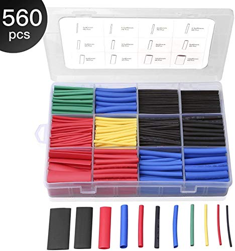
Heat-shrink
https://www.amazon.com/gp/product/B072PCQ2LW/ref=ppx_yo_dt_b_asin_title_o09_s00?ie=UTF8&psc=1
________________________________________________________________________________________________________________
Now follow this guide to put it together:
https://learn.adafruit.com/lightsaber-featherwing/circuit-diagram
We're not using a neopixel, so don't worry about that part. Just stick with the LED wiring. This part will take experimentation, so take your time and test-test-test. This guide will help with additional wiring and coding questions:
https://learn.adafruit.com/adafruit-prop-maker-featherwing
Now use this code if you're doing a color changing blade. If you're not, you can keep the code as is, and just manually set the saber color you desire:
https://github.com/robert1233/lightsaber/blob/master/code.py
And you should be good to go! I'm still working on perfecting the code. I'm still learning as well, but this works. The guide I based this off is:
https://learn.adafruit.com/lightsaber-featherwing/software
_______________________________________________________________________________________________________________
Features: micro-USB charging, color changing blade, sound and motion sensor for: startup, shut down, idle, swing, clash. Light up power button.
Cons: This has only been tested with a full-size ultrasabers blade. The LED could be brighter. I'm still working on that.
______________________________________________________________________________________________________________
Tips:
Sound files that I used can be found here. Use at your own discretion:
https://www.fx-sabers.com/forum/index.php?topic=41379.0
The hardest part of this build is the soldering. If you are comfortable with that and you are willing to do some reading, this is very easy to do. I had pretty much no electronic background and was able to figure all this out in about a month.
Make sure you use the short headers for soldering the feather and wing together! This is very important or the microcontroller may not fit into your hilt! Test twice, solder once.
Don't veer off the wishlist. Everything I picked is low profile and allows for maximum space and flexibility. I went with as much plug and play as I could. The battery, speaker, and charger are all plug-ins. The LED, power button, and color-changing potentiometer require soldering.
If you are going the color changing route, you may have to drill a hole wherever you want the color-changer to be.
______________________________________________________________________________________________________________
I'll upload photo's whenever I can. Like I said, I'm working on finding a better lighting source, so right now everything is taken apart.
_______________________________________________________________________________________________________________
I take no responsibility if you shock, burn, or stab yourself; or ruin your lightsaber or any electronic components. This is a guide on how I made the inside of my lightsaber and no more.
https://www.amazon.com/gp/product/B00K67YO8G/ref=ox_sc_act_title_5?ie=UTF8&psc=1&smid=A3G3SQGWUPUX9W is a switch I've seen used. As long as your batteries don't rhyme with schmustfires.
Yeah, I used a formlabs printer to resin print the tops and bottoms separately. I sanded with 400-3000 grit sandpaper in addition to using autobody spray paint filler, to help get a smooth finish.
In terms of room inside...there isn't much. BUT, if you use the proper wires (https://www.amazon.ca/gp/product/B00GWFECWO/ref=oh_aui_detailpage_o00_s00?ie=UTF8&psc=1) it's tight, but not a huge issue. Just take into account that you want NO slack wire hanging around in there.
Well my Stryfe has a pair of MTB Rhino motors instead of the stock ones. They're 12v instead of the 6v stock motors, and run on a 3S LiPo battery instead of the four AAs in series it normally takes.
1.5v * 4 = 6v max vs the LiPo at 12.6v max
I made this to help it fit.
Keep in mind that you need to redo the wiring with something thicker to keep from burning it out. And replace the stock trigger switch with something heavier, I think I used one of these.
I put a little voltage meter on connected to the jam door as well, so I know when it's running low.
So basically I've completely replaced all of the electrical components but it sure hits a lot harder now. You can actually get some decent range from it.
If I wanted to mess with it further I'd probably replace the flywheels with something that could grip a bit better, but the problem I ran into messing with it last time was if they grip too hard they shred darts.
I think this could make a sizable difference in noise. Mine really helped
3A Variac Variable AC Power Transformer 0~130 VAC by Parts Express
http://www.amazon.com/dp/B00BXJYO6I/ref=cm_sw_r_udp_awd_NGuwtb0A7R1N0
FWIW, I first used an old set of rabbit ears with my dongle (along with a mcx to f adapter) when I first got it. While it is certainly not optimal, it works well enough for broadcast FM and my local police/fire/EMS.
Foot pedal switch from Amazon, my dude.
Or OP could use this: https://www.amazon.com/PCS-Load-Resistor-Lighting-ILR-10K/dp/B01ES0AYU8
i can appreciate a real hardwood floor...
https://www.amazon.com/ThreeBulls-240pcs-29-5mm-18-5mm-Battery/dp/B01I6OU8YY/ref=lp_15069575011_1_2?srs=15069575011&ie=UTF8&qid=1493095501&sr=8-2
amazon prime, you can have em in 2 days... and youll have enough wraps for a lifetime, and enough to give out to others who need them...
I must be confused about how switches are rated. This was is listed as a 15A rating. Which should be adequate right? Or maybe you were meaning that for the given size of the switch it could have a higher amp rating?
You can solder or there are a variety of solderless connectors out there. A lot of people take the opportunity while they're replacing the fan to add in some type of connector (JST is popular and fine for something low current like a fan) to make any future swaps easier. If you're a bit timid about soldering you can use something like this - solder shrink connectors. I've never used them but have seen folks on another printing group recommend them. They're pretty much just shrink wrap with a bead of solder in the middle, you just stick the two wires in and heat. It solders and shrink wraps them all in one easy step.
https://www.amazon.co.uk/240v-110v-Step-Down-Transformer/dp/B000NIYH94
> Yamaha YAS-101
sorry, I didn't register that it was in your title. can you post a picture of your turntable's rear panel? I'm having trouble finding information on it on google. your soundbar doesn't have analog inputs, so you're gonna need an analog to digital converter, unless your turntable has digital outputs, which it sounds like it doesn't
if your turntable has a phono stage, you just need to convert RCA to TOSLINK, something like this analog to digital converter would work
if your turntable doesn't have a phono stage, you'll need one of those as well. so you'd need this phono stage as well as the aforementioned Analog to Digital converted
You may need a step down transformer. Something like this
Don't buy cheap with this sort of thing.
IIRC the Dolby Headphone effects aren't applied to the MP3 port. Just something to note. You're only going to get basic stereo sound.
To get surround, you'd either want the old Mixamp, which had analog stereo game inputs, or you can use something like this which will let you hook it up to the optical input.
I've been looking at
this: MCP3008
and
this: Using A Joystick On The Raspberry Pi Using An MCP3008
Reckon that could work?
This might be overkill for what you're trying to do, but...
Monoprice has a 6 zone amplifier. When you say "bluetooth and Alexa compatible," do you mean you want to connect to the speakers with an Echo via Bluetooth? Because if you hardwire the Echo to the amp, this negates the need for a bluetooth receiver, and in fact, the Echo can serve as a bluetooth receiver.
As for your TV sound bar question, the linked amp has pre-amp outs, which you could convert to optical using something like this box.
Does this make sense?
Note: I haven't personally used the products linked, but they are generally well reviewed.
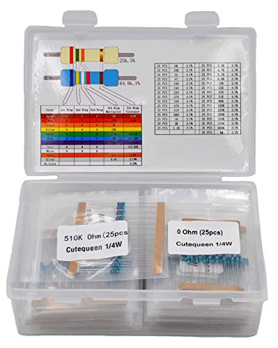
It depends on the component. Resistors and caps usually either work or not, and even really cheap sets tend to be within rated tolerances. I just buy the cheapest sets of those that have the values I want.
Transistors and ICs will depend on what you're getting. Common and still produced values are cheap and easy to get. Again, just buy whatever's cheap and gets you what you need. Watch out for fakes or seconds when buying out-of-production parts like 308s or 3007s. Best to get those from reputable places (smallbear, Mammoth, etc), because they're expensive and it's easy to get burned. I'd really look at the values you're getting when ordering ICs and possibly transistors in bulk. Those parts are usually really specific to a build and buying a lot of values might leave you with a bunch of unused parts.
The Joe Knows sets are good, if a little expensive. They tend to be well sorted, which is nice, but not something I'm willing to pay more for. Like this set of resistors is going to be just as good and is significantly cheaper than the equivalent Joe Knows set. There's certainly nothing wrong with the Joe Knows stuff though - if it has the values you need at the right price, go for it.
You can also score some great bulk deals on ebay and alibaba, but you'll be stuck waiting for overseas shipping a lot of the time. I'd go Amazon for an initial order and then shop around when you refill.
I'm not clear what you mean by I/O board? If it's just the gpio header on the pi itself, it's 3.3v but at 10mA, maybe 12mA? Enough to drive a signal, but not enough to energize a coil. (If you do have a separate board, you'd have to either lookup the specs for it, or let us know which one so we can figure it out.)
So you'll need something to use that to push a relay. Typically a darlington pair, an optoisolator, or a trip to Amazon.
I'm cheap and lazy, so I regularly use either these, which are 3v modules, or these which are awesome, but do need 5v drivers (I usually use an MCP23018 between the pi & the relay board - you'll find a shedload of documentation for this on the googles, but I'll shout-out adafruit's docs specifically). For the sainsmart ones, when they say 12V, they mean you'll need a separate 12V supply to push the relays themselves, they're not expecting 12V from the pi.
These will get the pi to drive n/c & n/o dry contacts you're used to, but I note you also asked about triggers - relay boards won't help protect inputs, so be warned that the inputs are also 3.3v and have very little tolerance (5v will kill them, let alone 24V. Anything you put in the IO lines goes straight into the CPU, so be gentle).
A couple of projects you might want to look into if you want to let someone else worry about the interfaces;
I think so.
https://www.amazon.com/Waveshare-4inch-HDMI-LCD-Resolution/dp/B01M07K5QQ/
Sure. You can do it a couple ways -
I HIGHLY recommend cutting off the cheap female spades that are on the Katana's speaker leads and replacing them with some crimp on INSULATED female spades like these:
https://www.amazon.com/Yueton-100pcs-Insulated-Terminal-Connectors/dp/B010GWZOUW/ref=pd_lpo_vtph_60_bs_t_1?_encoding=UTF8&psc=1&refRID=3X943RD62DVH2NFTZ8RZ
You can find them at any hardware store, and will protect the spades from touching each other if you accidentally turn the Katana on without having the leads connected to a speaker and prevent them from shorting between each other and damaging your Katana.
Yup, I bought a 240 pack in all different colors, and just give them away, and help apply them for anyone I know who might need one.
Somebody on the IRC channel pointed me towards this item, if anybody else has the same issue.
The singer 9960 is much better and has a metal frame, you need the updated one with the blue wavy lines, the old version without the lines was a dud so they fixed it and put the blue on. You can get them on the American ebay and they are cheaper even with import fees and shipping. What you want is a 300w step down transformer, I believe you are the same as the UK and 240w - in this case this is the type you need.
Also, continuous vote tallies are suuuper duper close to being ready to go, and I got the ADC I need to get moisture monitoring set up, sometime...
Don't. Use something like these.
I'm sure you could find them cheaper on Aliexpress or eBay, but I use these exact ones with NodeMCUs, WeMos D1 Minis, and WeMos D1 Mini Lites all the time. They work great.
https://smile.amazon.com/gp/product/B00ZSA83EW/ref=oh_aui_detailpage_o01_s00?ie=UTF8&psc=1
I use this: http://www.amazon.com/gp/product/B00GWFECWO
Cheap, multicolor.
Real kynar insulated wirewrap wire is much nicer and the insulation does not melt like this vinyl stuff does, but it's expensive.
limit/home switches if you want them (you should)
an e-stop - you probably have this
fan for the electronics case
power switch/plug for the power supply - you probably have this
connectors for wires (eg to get e-stop and limit switch wires into the case and connected. I use xlr plugs like These and these.
I also use these to help with wiring the limit/home switches in the case, but you may not need them, depending on what you use.
I replaced my hotend fan with this
https://www.amazon.com/gp/product/B00ZSA83EW/ref=oh_aui_detailpage_o01_s01?ie=UTF8&psc=1
I can't speak to if it would work but amazon has them
https://www.amazon.com/gp/aw/d/B016NXK6QK/ref=mp_s_a_1_3?ie=UTF8&qid=1526339191&sr=8-3&pi=AC_SX236_SY340_FMwebp_QL65&keywords=resistor&dpPl=1&dpID=412RenH-PlL&ref=plSrch
Ok. My first go at it was a DIY tent out of PVC pipe and panda film. It worked well, except near the end I did not have enough air flow, the whole things grew up into the light and went tits up.
I spent a TON of time designing what I wanted in the space I could fit it in. I used autodesk homestyler. http://www.homestyler.com/designer I'm not going to share it, because I didn't even end up using the design. I have a big ass pipe that runs though it, so I rotated everything 90 degrees to accommodate for it.
Here is the mini tour of my area. the drawing is in google draw and was to help me with my plumbing situation.
http://imgur.com/a/hTpgW
anyway, the main outer walls are cement or drywall. The inner is 3/4" PVC. If I had to do over, I'd go with 1" PVC. I started with Reflectix over the pvc. This was still letting some light leak though the material, so I went and put an inner layer of panda film over it.
The doors are pvc style doors for a greenhouse. I'm not too happy with them and I'll redo them at some point, but they work for now. Better than a zipper.
Electric. I ran a 20 amp circuit just for the room. I put outlets everywhere, but I still could have used a few more.. plan for everything, I put one outlet up high for a circulation fan, wish I did a second.
Plumbing. I ran it right into my res. I pump back out into the 3" pipe running overhead. No sink... yet.
Light is a 600w ipower. I'd probably go LED if I was going to buy again.
The system is a 3x3 ebb and flow tray. I'm running 10 plants right now. I want to just get a viable mother plant. I'm going for 3 strains, so I have to do it 2 more times. After that I will clone 36 plants in 6" netpots. One strain at a time.
I use the lucas formula for nutes with General hyponics maxibloom
http://lucasformula.com/
your fan looks good. I have one of these to go with mine: http://www.amazon.com/gp/product/B00BXJYO6I/ref=oh_aui_search_detailpage?ie=UTF8&psc=1
I like nirvana seeds. https://www.nirvanashop.com/en/13-indoor-marijuana-seeds
Other than that, I would say make a DIY tent first out of PVC and panda film. Get 1 grow under your belt and then build something out of wood. Let me know how it goes.
No, it doesn't matter at all, you just need a 12 volt power source like the cigarette lighter receptacle. There are also a lot of car modification shops if you want someone to do the installation for you.
If you want to just get one of the inexpensive backup cameras from Amazon you should check out some video tutorials to get started. Some people power the camera off of the reverse light (you know, the white lights on the back of cars when they go in reverse). That means that the camera stays off until you go into reverse. Personally I just leave my camera on, so I power everything off of my Cigarette Lighter Receptacle. Here are the parts I used:
A camera and monitor.
A cigarette lighter receptacle adapter.
A terminal strip. (This connects the cigarette receptacle to the camera and monitor).
Extension cable to connect your camera to your terminal strip.
Wire crimp connectors to connect the camera to your extension cable.
Optionally, but recommended: A cigarette receptacle splitter so you have extra power ports.
Sorry if my way of doing it is a little hacky, but it works. Let me know if you have any questions.
Jeg har et par af dem fra en kit.
https://www.amazon.co.uk/Adafruit-MCP3008-856-Converter-Interface/dp/B00NAY3RB2/ref=mp_s_a_1_1?imprToken=8T6MevTUTkATMIt6M60Umw&keywords=MCP3008&linkCode=g13&qid=1563247307&s=gateway&sr=8-1
If you're using a 2-wire dimmer like the older GE 45612, that normally can only be used with incandescent bulbs since a little bit of power flowing through the filament of the bulb provides the necessary juice to power the Z-wave circuit in the switch. If you switch to older incandescent bulbs, the problem should be solved.
On the other hand, if you have to have LED bulbs and you want to experiment a little, you could try installing the PCS load resistor. This was originally designed to treat flickering problems with dimmable LEDs but it would probably work for your situation too. HOWEVER, you'll need to install it at the light fixture since the leads must be connected to neutral and load wires... and you don't have a neutral at your switch location.
Just need yourself a deadman switch and you're set! I have one of these for my proxxon, so much more productive to just hit a pedal and you're ready to rock.
MLCS 9080 Billy Pedal Foot Switch, Deadman Style https://www.amazon.com/dp/B000LJNJOE/ref=cm_sw_r_cp_apa_i_L-AxDb30R8P11
what about this? https://www.amazon.com/SODIAL-Microswitch-V-156-1C25-plunger-action/dp/B00K67YO8G
ah thanks! ive just been looking those up and it looks like youre right (mine cuts the sine wave to reduce power). this there one anyone can recommend? something like this maybe?
A cable tie is pretty reversible. A foot-operated dead man switch would help, safety-wise, something like this...
http://www.amazon.com/MLCS-9080-Billy-Switch-Deadman/dp/B000LJNJOE/
What about this? https://www.amazon.com/Waveshare-4inch-HDMI-LCD-Resolution/dp/B01M07K5QQ/ref=sr_1_5?keywords=4+inch+screen&qid=1563986896&s=gateway&sr=8-5&utm_source=share&utm_medium=ios_app
Wow, yeah thats super small. That looks like something that has a specific purpose. Check these out.
https://www.amazon.com/Double-Sided-Board-Prototype-Paxcoo/dp/B01N3161JP/ref=sr_1_1_sspa?ie=UTF8&qid=1522698761&sr=8-1-spons&keywords=perfboard&psc=1
EDIT: Found the problem. You searched for "Perf Board". Try "Perfboard". Here is the same thing on the DE amazon.
https://www.amazon.de/Aihasd-Lochrasterplatte-Lochrasterplatine-Leiterplatte-Universal/dp/B00VL1KHJQ/ref=sr_1_4?s=ce-de&ie=UTF8&qid=1522698858&sr=1-4&keywords=PerfBoard
amazon starter $20
proto practice boards
practice resistors
https://www.amazon.com/MLCS-9080-Billy-Switch-Deadman/dp/B000LJNJOE/ref=pd_sim_328_8?_encoding=UTF8&pd_rd_i=B000LJNJOE&pd_rd_r=TJS35078VTZT2MM39N06&pd_rd_w=jg3Wa&pd_rd_wg=1byKr&psc=1&refRID=TJS35078VTZT2MM39N06
this is the one I have, it's 15 amp
You're going to need a step down transformer. This kind of thing https://smile.amazon.co.uk/240v-110v-Step-Down-Transformer/dp/B000NIYH94/ref=pd_sbs_147_4/260-0762073-8654467
The device is rated at 69W, so you really need at least 150VA rating transformer to allow for power factor issues and startup inrush current. This one is 300W/VA, which may be a little too big, but should be a safe bet. You could likely get away with a 200W/VA model.
I don't think the frequency difference 50Hz vs 60Hz is going to be a big problem in this case. Unless anyone knows differently.
spade connectors and a crimper!
https://www.amazon.com/Yueton-100pcs-Insulated-Terminal-Connectors/dp/B010GWZOUW/ref=sr_1_23?keywords=spade+connectors+crimper&qid=1567634312&s=hi&sr=1-23
​
https://www.amazon.com/WGGE-Professional-crimping-Multi-Tool-Multi-Function/dp/B073YG65N2/ref=sr_1_4?keywords=wire+stripper+crimper&qid=1567634471&s=hi&sr=1-4
something like this and this
dumb question, would the kill-a-watt plug into the variac with the behmor plugged into the kill-a-watt? or behmor to variac to kill-a-watt to wall socket? (the latter does not make sense to me, but I am not a smart man)
1.
Which wires specifically? In general, I was planning on going for heat-shrink solder terminal connectors and crimp connectors.
One of the reasons I posted this is because there are quite a few connectors and I am still not entirely 100% sure what I need. Obviously when screwing something in to a screw terminal block, the ring crimp connectors. But when joining wires, I would prefer to use the heat-shrink-solder type, but there are also butts and blades (heh).
I bought this set of terminals, figured I'd need them anyways: Assorted crimp terminals
I am probably going to buy this set of solder terminals: Fancy solder terminals
I am pretty good at soldering (though usually circuit boards, not automotive wires, hence not entirely knowing what to do.) I have easy access to a heat gun as well.
2.
Well, both - the breaker goes on the battery, and it sets the maximum amperage for the entire new fuse block and everything attached to it. The fuses go for each individual circuit. I want to use just one fuse for each circuit, instead of having several different circuits sitting on the same fuse, largely for my own desire for neatness and debug-ability. I could have one main fuse instead of the main breaker, but I figure that they will serve the same function and I may as well go for the re-usable option.
I was going to go for this breaker: Fat breaker
That said, I bought this fuse kit, which includes up to a 35A fuse, which will be more than enough. I also bought this fuse holder, in case I decide to use one main fuse instead of one main breaker. (I figured I'd need both of these anyways for some project, may as well get them even if I don't use them right now.)
Fuse Kit
In-line Fuse Holder
---
In general, I think my system will basically look like this:
Battery 12V + Breaker = safe 12V
Save 12V + ignition 12V (do I need a fuse here?) + Relay = ignition-switched 12V
Ignition-hot 12V + Fuse Block + ATC/ATO Fuses = eight fused circuits
Fused circuits, obviously, feeding from above. I will probably add a 20A switch in line with high-power circuits, just in case, as an emergency switch.
Fused circuits will terminate at something like this Ground Bar.
 
What do you think of this proposed setup?
I do realize that it's kind of overkill for what I want.
But you can probably agree that overkill is better than your car burning down!
If it doesn't have to be something that can be disconnected easily, then this might work: https://www.amazon.com/dp/B01M0EZBYQ
Practice on some spare wires first. Takes a bit of trial and error, but then works great.
Not being able to disconnect might be against code. But then, it's only low voltage. So, probably not a big deal
The first item looks like a good starting point for having a small collection of components and a breadboard to test your circuits. Unfortunately if you are looking to get some practice with soldering you are missing an important piece: the actual circuit board. I also use a lot of Pin Headers in my projects, but I like to make things modular and adaptable, so the headers might not be 100% necessary for everyone.
I have a screen very similar to that, and I never use it, since most of my projects are headless, and I just SSH into my Pis remotely. But people are different, you may get a lot of use out of it.
I would also say that you don't need the anti-static mat. Not to downplay ESD, because it can certainly harm your electronics, but you would be much better served with a wrist-strap that clipped onto your computer case or something else that is grounded in your work area.
No I mean shrink wrap.
https://www.amazon.com/dp/B072PCQ2LW/ref=cm_sw_r_cp_api_TaY7BbYWB0K24
"I'm so pissed off. Who's gonna replace my brand new ruined batteries? I have no way of wrapping them myself. If I added tape to my battery they will 100% not fit anymore into the mods."
YOU ARE.
Fucking woe is me, man.
Go on amazon and get some battery wraps, here's 240 in assorted colors for $10. https://www.amazon.com/ThreeBulls-240pcs-29-5mm-18-5mm-Battery/dp/B01I6OU8YY/ref=sr_1_4?ie=UTF8&qid=1538600861&sr=8-4&keywords=18650+battery+wrap
Enjoy!
Nice switches.
How many do you have to mount?
1-5: and glue them in.
6-20: buy prototyping boards , solder switches and drill holes to mount them.
20+: design a small pcb with mounting holes and have it made in china.
Indeed I am.
The specific one I bought was this: https://www.amazon.com/dp/B01M07K5QQ/
There's additional information on the Waveshare wiki here: http://www.waveshare.com/wiki/4inch_HDMI_LCD
If you go to the wiki and scroll down to the 'Driver Installation' section, you'll note the hdmi_cvt is set to 480 800. I didn't really think much of it at the time, as i assumed it was either a) a typo, b) you could initialise it as 800 480.
Unfortunately it's definitely portrait. If you attach it to anything else, it always starts in portrait mode and then you can use whatever you're running to rotate.
It is a massive shame that it doesn't work as you'd like. As it's an IPS display, the picture quality is simply excellent. It's crystal clear and vibrant. Unfortunately, it's also the wrong orientation...
I've replaced it was a 5 inch display and it's nice, but you can tell the panel is nowhere near as good. It just lacks the vibrancy.
Shame you can't have both really :-/
Sorry about the offtopic:
What is the difference between that fan and this one? I notice that some people use one model and other people use another. On the other hand, I want to update my fans to use the petfang. How many do I need and what model?
​
https://www.amazon.com/NTE-Electronics-77-4010D24-Bearing-Thermal/dp/B00ZSA83EW/ref=mp_s_a_1_5?ie=UTF8&qid=1545255710&sr=8-5&pi=AC_SX236_SY340_FMwebp_QL65&keywords=40mm+24v+fan&dpPl=1&dpID=41tCTbfHu8L&ref=plSrch
I don't have any experience with any other crimpers than the ones I mentioned above but these are pretty highly rated. You might also consider using heat shrink/solder butt connectors. I've got the kit I linked to here and have been impressed with it. You will need a heat gun though but no crimping involved. Just use enough heat to melt the solder and shrink the heat shrink .
Small screen for displaying system info: https://www.amazon.co.uk/Waveshare-4inch-HDMI-LCD-Resolution/dp/B01M07K5QQ/ref=pd_rhf_gw_p_img_3?_encoding=UTF8&psc=1&refRID=S1AQN4SG662XZZPC67DJ
You, Sir... need to be turned on to these:
http://www.homedepot.com/p/Tyco-Electronics-DuraSeal-Butt-Splices-22-18-10-Clam-Heat-Shrink-CPGI-D-406-0001-10/202204344
They've got these, too... which are pretty awesome(Heatshrink with solder!):
https://www.amazon.com/Shrink-Solder-Sleeve-Crimpless-Connectors/dp/B01M1032A7
100-200 Ohms seems about right. But I recommend buying a resistor kit like this instead of the individual values, makes you more flexible for future projects. And it's even cheaper than the 2 single value stips you listed.
Those earbuds have no stress relief in the connection. It is not your fault they are breaking. You just need to heat shrink for some stress relief.
Heat Shrink Tubing, Eventronic Electrical Wire Cable Wrap Assortment Electric Insulation Heat Shrink Tube Kit with Box(5 colors/12 Sizes) https://www.amazon.com/dp/B072PCQ2LW/ref=cm_sw_r_cp_apa_i_U6uRDb148T5HS
Method https://youtu.be/oHbgAiKBpf8
Do this to the points you feel are being tugged at. But do this for new earbuds, the old ones need to be fixed.
My thought would be to move the hunter up about a foot. I have opened mine once since i installed it..
Replace (or close up the knock outs) the HV box with a new one. Run flex out the bottom up to the hunter power.
https://imgur.com/a/iwK4rPp
Between the LV box and the hunter add another box (9x9). Splice via terminal strip in this box
Some thing like https://www.amazon.com/Position-Terminal-Postions-Insulated-Barrier/dp/B010UDG6NG
Not noticeable
I use a very simple and cheap one, looks like this
https://www.amazon.com/avedio-links-Digital-Converter-Adapter/dp/B00N8UYGMW/ref=sr_1_8?crid=2VFOBMU4APTO0&keywords=toslink+analog+to+digital&qid=1554578709&s=gateway&sprefix=toslink+analog%2Caps%2C234&sr=8-8
If you have stuff that requires 120V (American standard) and you go to a country with stuff thats up in the 200s (Europe, Asia, basically everywhere else you are likely to go with lots of electronics), then your 120V stuff might blow up. You need a step-down transformer like this: www.amazon.co.uk/240v-110v-Step-Down-Transformer/dp/B000NIYH94
Which is obviously massive and i doubt you'll want to carry that around. Far better to leave your 120V-only stuff at home. There's also a 50Hz or 60Hz frequency difference, but that usually doesn't have an effect unless you have stuff with AC motors in it (maybe your hair dryer?), in which case it will spin slightly slower in 50Hz countries.
The fan speed controller from the starter shopping list on the sidebar was a total piece of garbage. At first I thought the problem I was having was from my inline fan but after goin through 3... three goddamn fans it turns out that the controller was jacking things up. Started working fine but after a few weeks I could hear the fan that is in the basement all the way up on the 2nd floor.
Did some research n questioning that led me to buy a Variac Variable AC Power Transformer. It is pricey as a fill in for a fan speed controller but 8 months have passed with no issues.
This is on a 400watt setup. You may need a beefier transformer for a larger grow room. Be safe.
Thanks guys. Again, didn’t know it was an issue. Just bought a set of wraps from amazon. Will be here Sunday. Have a heat gun so it should be smooth sailing.
ThreeBulls 240pcs 12 Color 29.5mm 18.5mm PVC Heat Shrink Tubing Tube For 18650 18500 Battery Shrink Film https://www.amazon.com/dp/B01I6OU8YY/ref=cm_sw_r_cp_api_i_S9bcBbW648CGQ
The caseta pro dimmer with neutral should work with load capped. Dummy load would be something like https://www.amazon.com/PCS-Load-Resistor-Lighting-ILR-10K/dp/B01ES0AYU8
It's not good for weak signals or high current connections. If you don't want to use proper crimp joints, solder the wires inline, either by twisting the bare strands around each other or by straightening the strands and pushing them together so they interleave. With the latter, it may help to spiral wind a single fine strand of wire around the joint. Applying rosin flux to the joint before soldering can help a lot. Cover the joint with a piece of heatshrink tubing that's at least 1.5" longer than the bare area, both for insulation and mechanical support (soldered stranded wire is prone to cracking).
Another possibility is SoldaSplice. It's heatshrink tubing with a ring of solder in the middle. You insert the wires and use a heat gun to both melt the solder and shrink the tubing.
You're right, sorry. I am using the magnetic contact that came with Charlie's block, attached to the collet.
I'm not using an Arduino shield, but separate discrete drivers.
I appreciate the info on the pull-up/down resistor and the low pass filter but I'll be honest and tell you that you're speaking above my level of electronics knowledge. I'll do some reading on those topics and see if I can figure out what needs to be tried in those areas.
Do you think the optoisolator relay board will help? These are the ones I bought. I plan to have them actuated with a discrete power supply to isolate the Uno from the spindle as much as possible.
Ended up getting the transformerto fit in the old box. Working fine at 16V 30va setting of the transformer (vs 24V). Used 3 pairs of wire total with this heat shrink tubing and these heat shrink solder wire connectors. Thanks all.
Here is the mobile version of your link
Here is a quickly made fan blade based on a render of the Ender 3. It's assuming that your hotend fan blade broke, not part cooling. I have no clue if it will work or not. Use super glue to attach it. https://www.thingiverse.com/thing:3758044
Honestly, it probably won't work out well. You might consider a replacement fan from Amazon. But this might get you going.
Similar to what I'm trying....
Just ordered this last night:
https://www.amazon.com/gp/product/B00N8UYGMW/ref=oh_aui_detailpage_o00_s00?ie=UTF8&psc=1
My hope is to go monitor>beam.
Monitor 3.5 port > RCA Y cable > LinkS adapter link > Toslink/Digital optical > HDMI adapter included with the beam.
Not sure if that is exactly what you're looking for or not. But if so I can tell you tomorrow or the day after when it shows up.
Using this ADC and using this sensor hooked up to a raspberry pi and breadboard with pi cobbler type attachment. Still waiting on the ADC to come in from Amazon.
It depends on which dongle you have. TS9, MCX and SMA are the most common connectors I've seen.
I use this adapter on mine to connect to my QFH antenna with RG-6 coax and standard TV F connectors.
I am sorry, I have never used a dish. I did use an adapter so I could use coax cable with the dongle. This one: http://www.amazon.com/gp/product/B00CKG6T9I/ref=oh_aui_detailpage_o06_s00?ie=UTF8&psc=1
I had made the coat hanger HD antenna (look it up if you like) and had supplies for cutting it and adding ends/connectors.
As an affair of convenience I ordered other things that would let me use things I have on hand. I cannot tell you if this makes a big difference or not, but the the coax I got locally is all 75 ohm. There is 50 ohm too, but It is less common here. I am not sure it will make much of a difference. Maybe to some,but for us newbs, just get the cable man.
I bought the dongle and got it going with the mess of instructions above. Once it was working, I made the different antennas and checked them out. It seems like a lot, when you try to suck it all in. But if you go one step at a time, it is really not so bad. Go slow friend. It can work, and you will learn a bit along the way. Best wishes, I should never be considered an expert, but I have no problem talking about it all with you. I am sorry if it causes more confusion too, but we should be able to get you set up! I will try.
Love the push/pull analogy. Thanks for that one, makes sense. Kind of a supply vs demand situation.
Yes, same power supply but only interact via a relay: GPIO2 on ESP-01 goes high (+3.3v, remember I'm still learning terminology here) when triggered via message, opens 3.3v relay (https://amzn.com/B01M0E6SQM) which connects 12v via step-up to gate remote which has it's button locked on. So 5v source split into 3.3v step down and 12v step up, separated by the relay downstream.
The setup allows me to skip two important features: needing to deconstruct/integrate with the remote board to replicate a button press (which would have been destructive) and needing to power off a battery (would have required ongoing replacement & cost).